Design of Mixed-Voltage Crystal Oscillator Circuit
in Low-Voltage CMOS Technology
Ming-Dou Ker and Hung-Tai Liao Nanoelectronics and Gigascale Systems Laboratory Institute of Electronics, National Chiao-Tung University 1001 Ta-Hsueh Road, Hsinchu, Taiwan 300, R.O.C. [email protected] Abstract—In the nanometer-scale CMOS technology, the
gate-oxide thickness has been scaled down to support a higher operating speed under a lower power supply (1xVDD). However, the board-level voltage levels could be still in a higher voltage levels (2xVDD, or even more) for compatible to some earlier interface specifications in a microelectronics system. The I/O interface circuits have been designed with consideration on the gate-oxide reliability in such mixed-voltage applications. In this work, a new mixed-mixed-voltage crystal oscillator circuit realized with low-voltage CMOS devices is proposed without suffering the gate-oxide reliability issue. The proposed mixed-voltage crystal oscillator circuit, which is one of the key I/O cells in a cell library, has been designed and verified in a 90-nm 1-V CMOS process to serve 1/1.8-V mixed-voltage interface applications.
I. INTRODUCTION
In CMOS technology, the device dimension of transistors has been scaled toward the nanometer region, and the power supply voltage of chips in the nanoscale CMOS process has been also decreased to around 1V [1]. Obviously, the shrunk device dimension makes the chip area smaller to save silicon cost. The lower power supply voltage (VDD) results in lower power consumption. Therefore, chip design quickly migrates to the lower voltage level with the advancement of the nanoscale CMOS technology. However, some peripheral components or other ICs in a microelectronic system are still operated at the higher voltage levels for compatible to some earlier interface specifications. In other words, the interface circuits between two chips have to deal with the I/O signals in different voltage levels [2]-[4]. A complete I/O library includes the digital and analog I/O cells, power/ground cells and crystal oscillator cells. The design of mixed-voltage I/O circuits has been discussed and presented in some literatures [5], but the mixed-voltage crystal oscillator circuit was never mentioned before.
A conventional crystal oscillator circuit is connected with a crystal between the output (XO) pad and the input (XI)
*This work was supported by Research Project from the Ministry of
Economic Affairs, Taiwan, R.O.C., under Grant 96-EC-17-A-01-S1-037.
pad for oscillation to generate the stable clock signal for chip operations. In some applications, the clock signal will be directly provided from the external clock sources and sent into the chip through the input (XI) pad with the output (XO) pad floating. But, the conventional crystal oscillator circuit designed with 1xVDD CMOS devices is unsuitable to receive the external clock signal with voltage level over VDD, due to the gate-oxide reliability issue [6], [7] and the hot-carrier degradation issue [8].
In this work, a new mixed-voltage crystal oscillator circuit realized with low-voltage CMOS devices is proposed without suffering the gate-oxide reliability issue. The proposed mixed-voltage crystal oscillator circuit has been designed and verified in a 90-nm 1-V CMOS process to serve 1/1.8-V mixed-voltage interface applications.
II. PIERCE OSCILLATOR
The conventional Pierce-type crystal oscillator circuit is shown in Fig. 1 [9], [10], which consists of two parts. One is an inverting amplifier that supplies a voltage gain and 180-degree phase shift, which is integrated into the chip with the XI and XO pads. The other is a frequency selective feedback path, which is out of the chip. The crystal combined with C1 and C2 to form a feedback network that tends to stabilize the frequency and supply 180 degree phase shift to the feedback path. The feedback resistance, Rf, is used to bias the inverting amplifier around half of power supply voltage, therefore the inverting amplifier is operating in the high-gain linear region. In steady state, this circuit has an overall phase shift around 360 degree. This satisfies one of the conditions required to sustain oscillation. The other condition for proper start-up and sustaining oscillation is that the closed loop gain should be over or equal to one.
The equivalent circuit of a crystal is shown in Fig. 2. R is the effective series resistance in the crystal, as well as L and Cs are the motional inductance and capacitance of the crystal. Cp is the parasitic shunt capacitance due to the electrodes. In parallel resonant mode, the crystal will look inductive to the circuits. At the resonant frequency, the crystal will look and perform like a low resistance.
1121 1-4244-0921-7/07 $25.00 © 2007 IEEE.
Figure 1. Pierce-type crystal oscillator circuit.
Figure 2. The equivalent circuit of a crystal.
Figure 3. Reactance vs. frequency plot of a crystal.
Fig. 3 shows the reactance-frequency plot of the crystal. When the crystal is operating at series resonance, it looks purely resistive and the series resonance frequency (fs) is given by
(1) When the crystal is operating in parallel resonant mode, it looks inductive. The frequency of operation in this mode is defined by the load on the crystal. In this mode, the frequency (fa) of oscillation is given by
(2)
where the CL is
(3) Cstray is the stray capacitance on the printed circuit board.
III. GATE-OXIDE RELIABILITY ISSUE In the advanced CMOS process, the devices with thinner gate oxide can be operated at a higher operating speed under a lower VDD supply voltage. The power supply voltage level has been decreased from 2.5V to around 1V (or below) to maintain the gate-oxide reliability and to overcome the hot-carrier degradation. However, many other components on the board or in the system are still operated at another higher voltage level, such as 3.3V. This is also a challenge to the interface circuit to avoid the gate-oxide reliability problem.
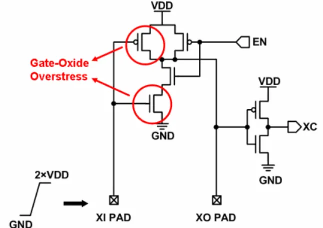
Fig. 4 shows the conventional crystal oscillator circuit realized with the 1×VDD devices. When this circuit was used in the mixed-voltage interface, it will suffer the gate-oxide reliability issues [6], [7]. When the EN signal is kept at VDD and the external input clock signal at the XI pad rises up to 2×VDD. The pull-up PMOS and pull-down NMOS will suffer the gate-oxide overstress issue. In order to avoid the gate-oxide reliability issue, the devices which suffer the gate-oxide overstress could be replaced by the thick-oxide devices. However, with both of the thick-oxide and thin-oxide devices in a chip, the fabrication cost of CMOS process is increased.
Figure 4. Conventional crystal oscillator circuit suffering the gate-oxide reliability issue when it receives a 2×VDD external clock signal.
IV. NEWPROPOSEDCIRCUIT
Fig. 5 shows the new proposed mixed-voltage crystal oscillator circuit realized with only thin gate-oxide (1xVDD) devices. XI pad and XO pad are the input and output pads of the proposed mixed-voltage crystal oscillator circuit, respectively. EN and PA signals are controlled by the internal circuits of IC. XC is the clock signal sending to internal circuit, which is produced by crystal oscillator circuit or by the external clock signal into the IC.
1
.
2
sf
LCs
π
=
1 , 2 a L P L P f C C L C C π = + 1 2 . 1 2 L C C C Cstray C C = + + i 1122A. Oscillation mode
When the voltage level of PA signal is VDD, the proposed mixed-voltage crystal oscillator circuit is operated with crystal and two load capacitances to generate the sinusoidal-wave signal at both XI pad and XO pad. Transmission gates TRAN1 and TRAN2 are turned off, so that the sinusoidal-wave signal can’t pass through the upper path of this circuit from XI pad to XO pad. Besides, transistor MN4 is turned on to keep transistor MN2 off and transistor MP3 on in order to keep the output terminal of the upper nand gate at VDD. The gate terminal of transistor MP4 is directly connected to the output terminal of the upper nand gate, so the transistor MP4 is turned off. The input terminal (N01) of the upper nand gate will follow the voltage level of XI pad, while the output terminal of upper nand gate keeps at VDD. Meanwhile, transmission gates TRAN3 and TRAN4 are turned on and the generated sinusoidal-wave signal will pass through the lower path of this circuit from XI pad to XO pad. The signal EN can be transmitted to one input terminal of the lower nand gate to enable or disable the lower nand gate. Besides, transistor MN7 and MP7 are turned off. B. Receiving mode
When the voltage level of PA signal is GND, the proposed mixed-voltage crystal oscillator circuit is operated to receive an external clock input signal whose voltage level could be 1×VDD or 2VDD. Transmission gates TRAN1 and TRAN2 turn on and the external clock signal will pass through the upper path from XI pad to XC. The signal EN can be transmitted to one input terminal of the upper nand gate to enable or disable the nand gate. Besides, transistor MN4 is turned off. Transistors MN1 and MP4 with upper nand gate are used to transfer the external clock signal from the XI pad to the XO pad. Transistor MN1 is used to limit the voltage level of external clock input signal reaching to the gate oxide of the upper nand gate. Because the gate terminal of transistor MN1 is connected to the power supply voltage (VDD), the input (N01) voltage of the upper nand gate is limited to VDD-Vt when the voltage level of external clock signal is even up to 2×VDD. Then, transistor MP4 will pull the input node (N01) of the upper nand gate up to VDD, when the output node of upper nand gate is pulled to GND. The external clock signal can be successfully transferred into the internal input node XC. Meanwhile, transmission gates TRAN3 and TRAN4 turn off. Transistor MN7 is turned on to keep transistor MN6 off and transistor MP6 on in order to keep the output terminal of the lower nand gate at VDD.
Transistor MP7 is also turned on to keep the node between MN5 and MN6 at VDD. Thus, when the XI pad is with the input signal voltage level of 2×VDD, any voltage drop between the gate terminal and source/drain terminal of transistor MN5 and MP5 is still limited to VDD. So, the new proposed crystal oscillator circuit can receive the external clock signal of 2×VDD without suffering the gate oxide overstress issue.
Figure 5. New proposed mixed-voltage crystal oscillator circuit.
(a)
(b)
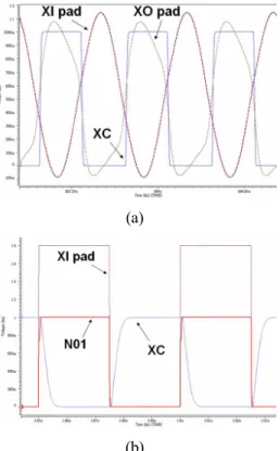
Figure 6. Simulated waveforms of the new proposed crystal oscillator circuit with (a) a crystal of fundamental frequency MHz and load capacitance pF (PA=VDD), and (b) 20-MHz external clock signal 2×VDD into XI pad and 20-pF load capacitance in XC (PA=GND).
C. Simulations
Fig. 6 shows the simulation waveform of the proposed mixed-voltage crystal oscillator circuit in a 90-nm 1-V CMOS process to serve 1/1.8-V mixed-voltage interface. In Fig. 6(a), the proposed mixed-voltage crystal oscillator circuit with the crystal of 20-MHz fundamental frequency and a load capacitance 20-pF at the pad can successfully 1123
generate the clock signal of 20 MHz at the XC node under the power supply of 1×VDD. As shown in Fig. 6(b), with the MHz external clock signal of 2×VDD into XI pad and 20-pF load capacitance in XC, the input terminal (N01) voltage of the upper nand gate can be limited and biased at the desired voltage level (1V). The final signal voltage level reaching to the XC node is successfully shifted down to 1×VDD. The proposed mixed-voltage crystal oscillator circuit can be operated correctly without the gate-oxide reliability issue. From these simulations, the desired functions of this mixed-voltage crystal oscillator circuit have been verified.
Figure 7. Layout view of new proposed mixed-voltage crystal oscillator circuit in a 90-nm CMOS process.
(a)
(b)
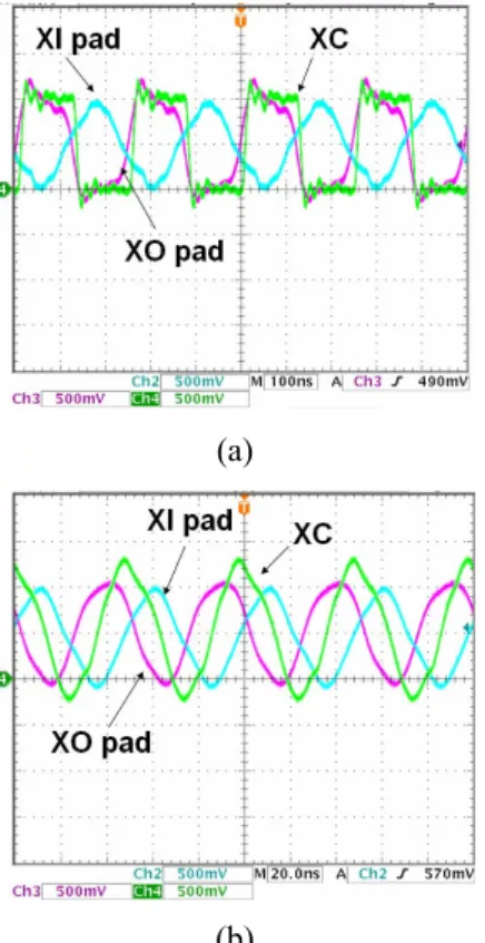
Figure 8. Measured waveforms of the new proposed mixed-voltage crystal oscillator circuit with a crystal of fundamental frequency at (a) 4-MHz and (b) 20-MHz.
D. Layout
Fig. 7 shows the layout view of the proposed mixed-voltage crystal oscillator circuit implemented in a 90-nm CMOS process. The cell size of XI, as well as XO, is only 190.5μm×60μm (including the bond pad), which is the same as that of digital or analog I/O cells in a standard I/O cell library. Feedback resistance Rf is also included and implemented by the poly resistance into the cell.
E. Measurement Results
The measured waveforms of the new proposed mixed-voltage crystal oscillator circuit, which has been fabricated in a 90-nm CMOS process, in the oscillation mode with 4-MHz and 20-MHz crystals and 20-pF load capacitance are shown in Figs. 8(a) and 8(b), respectively. As shown in Fig. 8, the clock signals of 4-MHz and 20-MHz can be successfully generated at the XC node by the sinusoidal waves at the XO pad. From the measurement results, the new proposed mixed-voltage crystal oscillator circuit can be operated correctly.
V. CONCLUSION
A new mixed-voltage crystal oscillator circuit realized with low-voltage CMOS devices has been proposed and successfully verified in a 90-nm CMOS process, which can be operated correctly without suffering gate-oxide reliability issue in the mixed-voltage interface applications. This design solution can be extended to other CMOS ICs with mixed-voltage interfaces in advanced nanoscale CMOS processes.
REFERENCES
[1] Semiconductor Industry Association, International Technology Roadmap for Semiconductors, 2006.
[2] J. Williams, “Mixing 3V and 5V ICs,” IEEE Spectrum, pp. 40-42, 1993.
[3] A.-J. Annema, G. Geelen, and P. C. de Jong, “5.5-V I/O in a 2.5-V 0.25-μm CMOS technology,” IEEE J. Solid-State Circuits, vol. 36, no. 3, pp. 528-538, Mar. 2001.
[4] G. P. Singh and R. B. Salem, “High-voltage-tolerant I/O buffers with low-voltage CMOS process,” IEEE J. Solid-State Circuits, vol. 34, no. 11, pp. 1512-1525, Nov. 1999.
[5] M.-D. Ker, S.-L. Chen, and C.-S. Tsai, “Overview and design of mixed-voltage I/O buffers with low-voltage thin-oxide CMOS transistors,” IEEE Trans. on Circuits and Systems I, vol. 53, no. 9, pp. 1934-1945, Sept. 2006.
[6] T. Furukawa, et. al., “Accelerated gate-oxide breakdown in mixed-voltage I/O circuits,” in Proc. IEEE Int. Reliability Physics
Symp., 1997, pp. 169-173.
[7] R. S. Scott, N. A. Dumin, T. W. Hughes, D. J. Dumin, and B. T. Moore, “Properties of high-voltage stress generated traps in thin silicon oxide,” IEEE Trans. Electron Devices, vol. 43, no. 7, pp. 1133-1143, July 1996.
[8] I.-C. Chen, J. Y. Choi, and C. Hu, “The effect of channel hot-carrier stressing on gate-oxide integrity in MOSFETs,” IEEE
Trans. Electron Devices, vol. 35, no. 12, pp. 2253-2258, Dec.
1988.
[9] A. Pauptit and W. Rosink, “Oscillators on 8-bit microcontrollers (2),” Philips Semiconductors, Netherlands, Application Note AN97090, Dec. 1997.
[10] A. Pauptit and E. Nordberg, “X-tal oscillators on 8-bit microcontrollers,” Philips Semiconductors, Netherlands, Application Note AN96103, Sep. 1996.