應用於數位電視廣播系統之低複雜度頻率同步化設計
86
0
0
全文
(2) 應用於數位電視廣播系統之低複雜度頻率同步化設計 Low Complexity Carrier Frequency Synchronization for DVB-T/H System. 研 究 生:簡盧忠. Student:Lu-Chung Chien. 指導教授:李鎮宜. Advisor:Chen-Yi Lee. 國 立 交 通 大 學 電子工程學系 電子研究所 碩士班 碩 士 論 文. A Thesis Submitted to Institute of Electronics College of Electrical Engineering and Computer Science National Chiao Tung University in Partial Fulfillment of the Requirements for the Degree of Master of Science in Electronics Engineering July 2005 Hsinchu, Taiwan, Republic of China. 中華民國九十四年七月.
(3) 應用於數位電視廣播系統之低複雜度頻率同步化設計. 學生:簡盧忠. 指導教授:李鎮宜 教授. 國立交通大學 電子工程學系 電子研究所碩士班. 摘要 在本論文中,我們提出了一個應用於數位電視廣播系統的低複雜度載波頻率同步化 設計。此同步化設計由兩組偵測機制及一組追蹤迴路組成。與傳統的演算法相比,我們 所提出的小數倍載波頻率漂移偵測機制可以有效的對抗多重路徑延遲造成的干擾,並且 在均方根錯誤可達到 0.25~7.8 分貝的信號雜訊比改進。在整數倍載波頻率漂移偵測機制 方面,我們所提出的二階段架構可以有效的減少偵測範圍以降低運算複雜度。此外,為 了偵測正確的整數倍載波頻率漂移值,我們提出了兩種低複雜度的演算法,在不影響整 體系統效能的前提之下,相較於傳統的演算法可以減少超過 80%以上的乘法次數。提出 的三階段載波頻率漂移追蹤迴路亦可有效的降低殘留的誤差。利用我們所提出的低複雜 度載波頻率同步化設計,對整體數位電視廣播系統平台而言,在嚴重的傳輸環境包括 Rayleigh 衰減通道、杜普勒頻率 70 赫茲、取樣頻率漂移百萬分之 20、載波頻率漂移百 萬分之 92.14 情況下,載波頻率同步化誤差造成的訊號雜訊比損失仍小於 0.2 分貝。基 於我們所提出的低複雜度載波頻率同步化設計,在 2005 年 6 月,我們使用 0.18 微米製 程實現了數位電視廣播系統基頻接收器的晶片設計。. i.
(4) Low Complexity Carrier Frequency Synchronization for DVB-T/H System Student:Lu-Chung Chien. Advisor:Dr. Chen-Yi Lee. Institute of Electronics Engineering National Chiao Tung University. ABSTRACT In this thesis, a low complexity carrier frequency offset (CFO) synchronization scheme is proposed for Digital Video Broadcasting-Terrestrial/Handheld (DVB-T/H) system, which comprises two acquisition strategies and a tracking loop. The proposed fractional CFO acquisition algorithm can overcome the distortion caused by multipath delay spread and achieves 0.25~7.8dB gain in RMSE compared with the conventional approach. A 2-stage scheme is proposed for the integral CFO acquisition to reduce the search range. Besides, two low complexity algorithms are also proposed to detect the accurate integral CFO value and save more than 80% of number of multiplication without any performance loss to the overall system compared with the conventional approach. The proposed three stage CFO tracking loop can reduce the residual CFO error effectively. The SNR loss due to the proposed CFO synchronization scheme of the overall DVB-T/H baseband receiver system is less than 0.2dB even in severe channel distortion including Rayleigh channel, Doppler spread 70Hz, CFO 92.14ppm (10.33 subcarrier spacing) and sampling clock offset 20ppm. Based on the proposed low complexity CFO synchronization scheme, a DVB-T/H baseband receiver is implemented with 0.18µm cell library and tapped out in Jun. 2005. ii.
(5) 誌. 謝. 從大三做專題以來,Si2 這個大家庭已經與我共度了三年多的時光。在這裡不但學 到了許多專業知識,為人處事方面更是受益良多。 能完成這本論文,我最感謝的,是 李鎮宜教授這三年多以來不厭其煩的指導與研 究方向的指引,讓我在研究遇到挫折或困難時,得以重新找到突破瓶頸的方法。此外, 也要感謝. 李鎮宜教授爲實驗室提供完善的研究設備,使我的研究得以順利完成。. 在這裡,也要特別感謝 DVB group 的黎峰學長、昱偉學長、陳元學長、成偉學長、 英豪以及家豪兩位學弟,感謝大家這兩年來的腦力激盪與相互討論,不但使我在相關的 研究領域有所精進,更學習到團隊合作的可貴。 還要感謝與我同屆的亭安、勝仁、凱立、林宏與瑋哲,在這兩年內,我們一起經歷 過許多風風雨雨,有歡笑也有淚水,有你們的陪伴,使我這兩年的碩士生涯充滿了多彩 多姿的回憶。 最後,我要由衷的感謝我的父母及家人,感謝你們多年來的栽培及細心,讓我能順 利完成碩士的學業。更要感謝我的女友舒慧,這幾年來有妳的一路相伴,使我的生活不 再孤單,更期待未來的日子裡,能與妳度過人生的旅程。僅將此論文獻給你們,以表達 我最深的感激。. iii.
(6) Contents. CHAPTER 1 . INTRODUCTION........................................................................................1 1.1. MOTIVATION ................................................................................................................1. 1.2. INTRODUCTION TO DVB-T/H SYSTEM.........................................................................2. 1.3. ORGANIZATION OF THIS THESIS ...................................................................................7. CHAPTER 2 . CARRIER FREQUENCY OFFSET SYNCHRONIZATION ALGORITHMS ........................................................................................................................8 2.1. INTRODUCTION TO CARRIER FREQUENCY OFFSET .......................................................8. 2.1.1. Signal Model of Carrier Frequency Offset .........................................................9. 2.1.2. Effect of Carrier Frequency Offset ...................................................................10. 2.2. CARRIER FREQUENCY OFFSET SYNCHRONIZATION SCHEME ......................................12. 2.3. FRACTIONAL CARRIER FREQUENCY OFFSET SYNCHRONIZATION...............................14. 2.4. INTEGRAL CARRIER FREQUENCY OFFSET SYNCHRONIZATION ...................................17. 2.4.1. Conventional Pilots Based Approach ...............................................................17. 2.4.2. Conventional Guard Band Based Approach.....................................................20. 2.4.3. Proposed 2-stage Approach..............................................................................22. 2.4.4. The First Stage of the Proposed Approach.......................................................23. 2.4.5. The Second Stage of the Proposed Approach ...................................................24. 2.5. RESIDUAL CARRIER FREQUENCY OFFSET SYNCHRONIZATION ...................................27. 2.5.1. Residual CFO Estimation.................................................................................28. 2.5.2. Residual CFO Tracking Loop Filter.................................................................31. CHAPTER 3 . SIMULATION AND PERFORMANCE ANALYSIS .............................33 iv.
(7) 3.1. SIMULATION PLATFORM.............................................................................................33. 3.2. CHANNEL MODEL ......................................................................................................36. 3.2.1. Multipath Fading Channel Model ....................................................................37. 3.2.2. Doppler Spread Model .....................................................................................39. 3.2.3. Carrier Frequency Offset and Sampling Clock Offset model...........................40. 3.3. PERFORMANCE ANALYSIS ..........................................................................................41. 3.3.1. Fractional Carrier Frequency Offset Synchronization.....................................42. 3.3.2. Integral Carrier Frequency Offset Synchronization.........................................46. 3.3.3. Residual Carrier Frequency Offset Tracking ...................................................55. 3.3.4. Overall System Performance ............................................................................58. CHAPTER 4 . ARCHITECTURE AND IMPLEMENTATION.....................................62 4.1. DESIGN METHODOLOGY ............................................................................................62. 4.2. ARCHITECTURE OF THE DVB-T/H BASEBAND RECEIVER .........................................63. 4.3. ARCHITECTURE OF CARRIER FREQUENCY OFFSET SYNCHRONIZATION .....................66. 4.3.1. Fractional Carrier Frequency Offset Synchronization.....................................66. 4.3.2. Integral Carrier Frequency Offset Synchronization.........................................67. 4.3.3. Residual Carrier Frequency Offset Tracking ...................................................69. 4.4. DVB-T/H BASEBAND RECEIVER CHIP SUMMARY .....................................................70. CHAPTER 5 . CONCLUSION AND FUTURE WORK..................................................72 BIBLIOGRAPHY...................................................................................................................73. v.
(8) List of Figures FIG. 1.1 FUNCTIONAL BLOCK DIAGRAM OF DVB-T SYSTEM .......................................................3 FIG. 1.2 BLOCK DIAGRAM OF DVB-H CODEC AND TRANSMITTER ...............................................5 FIG. 2.1 SPECTRUM OF FIVE ORTHOGONAL SUBCARRIERS OF OFDM SYSTEMS ............................8 FIG. 2.2 PHASE ROTATION IN TIME DOMAIN FOR LONG TIME RECEPTION WHEN Ε=0.01 .............. 11 FIG. 2.3 SPECTRUM OF FIVE SUBACRRIERS IN CARRIER FREQUENCY OFFSET ENVIRONMENT ...... 11 FIG. 2.4 OVERALL CFO SYNCHRONIZATION AND COMPENSATION SCHEME ................................13 FIG. 2.5 GUARD INTERVAL INSERTION AND MULTIPATH CHANNEL SPREAD..................................15 FIG. 2.6 RECEIVED SIGNAL IN FREQUENCY DOMAIN WHEN CFO=1 SUBCARRIER SPACE.............18 FIG. 2.7 RECEIVED SYMBOL IN FREQUENCY DOMAIN WHEN CFO IS -2.......................................21 FIG. 2.8 PROPOSED 2-STAGE INTEGRAL CFO ALGORITHM SCHEME ............................................22 FIG. 2.9 THE FIRST STAGE OF THE PROPOSED INTEGRAL CFO ESTIMATOR ..................................23 FIG. 2.10 THE PROPOSED GUARD BAND POWER DETECTION BASED APPROACH ..........................27 FIG. 2.11 THE TRACKING LOOP OF THE CFO SYNCHRONIZATION ...............................................28 FIG. 2.12 PHASE ROTATION BETWEEN TWO SUCCESSIVE OFDM SYMBOLS ................................30 FIG. 2.13 BLOCK DIAGRAM OF PI LOOP FILTER ..........................................................................32 FIG. 3.1 OVERALL DVB-T/H PLATFORM ...................................................................................33 FIG. 3.2 THE BASEBAND RECEIVER DESIGN ................................................................................35 FIG. 3.3 FUNCTIONAL BLOCKS OF INNER RECEIVER....................................................................36 FIG. 3.4 CHANNEL MODEL OF DVB-T/H SYSTEM ......................................................................37 FIG. 3.5 CHANNEL RESPONSE OF RAYLEIGH AND RICEAN (K=10DB) CHANNEL ........................39 FIG. 3.6 DOPPLER SPREAD MODEL .............................................................................................39 FIG. 3.7 BER PERFORMANCE IN DIFFERENT CFO ERROR ...........................................................41 vi.
(9) FIG. 3.8 RMSE PERFORMANCE IN DIFFERENT GUARD INTERVAL LENGTH ..................................43 FIG. 3.9 RMSE PERFORMANCE IN DIFFERENT Y .........................................................................44 FIG. 3.10 RMSE PERFORMANCE COMPARISON ..........................................................................45 FIG. 3.11 PERFORMANCE OF THE FIRST STAGE WITH DIFFERENT WINDOW WIDTH .......................47 FIG. 3.12 PERFORMANCE OF THE FIRST STAGE IN DIFFERENT CHANNEL MODELS ........................48 FIG. 3.13 CONTINUAL PILOTS BASED APPROACH WITH DIFFERENT NUMBER OF PILOTS ..............49 FIG. 3.14 PROPOSED GUARD BAND BASED APPROACH WITH DIFFERENT WINDOW WIDTH ...........50 FIG. 3.15 PERFORMANCE OF DIFFERENT INTEGRAL CFO ESTIMATORS IN GAUSSIAN CHANNEL .51 FIG. 3.16 PERFORMANCE OF DIFFERENT INTEGRAL CFO ESTIMATORS IN RICEAN CHANNEL ......52 FIG. 3.17 PERFORMANCE OF DIFFERENT INTEGRAL CFO ESTIMATORS IN STATIC RAYLEIGH CHANNEL ...........................................................................................................................53. FIG. 3.18 PERFORMANCE OF DIFFERENT INTEGRAL CFO ESTIMATORS IN MOBILE RAYLEIGH CHANNEL ...........................................................................................................................54. FIG. 3.19 RMSE OF ONE-SHOT RESIDUAL CFO ESTIMATOR IN DIFFERENT CHANNEL MODELS ...56 FIG. 3.20 CFO TRACKING LOOP IN WITH DIFFERENT PARAMETERS.............................................57 FIG. 3.21 RESIDUAL CFO TRACKING LOOP WITH DIFFERENT STAGE...........................................58 FIG. 3.22 OVERALL SYSTEM PERFORMANCE IN GAUSSIAN CHANNEL .........................................59 FIG. 3.23 OVERALL SYSTEM PERFORMANCE IN RICEAN CHANNEL .............................................60 FIG. 3.24 OVERALL SYSTEM PERFORMANCE IN RAYLEIGH CHANNEL .........................................60 FIG. 3.25 OVERALL SYSTEM PERFORMANCE IN MOBILE RAYLEIGH CHANNEL ............................61 FIG. 4.1 PLATFORM-BASED DESIGN METHODOLOGY ..................................................................63 FIG. 4.2 ARCHITECTURE OF THE DVB-T/H BASEBAND RECEIVER .............................................65 FIG. 4.3 ARCHITECTURE OF FRACTIONAL CFO ESTIMATOR ........................................................66 FIG. 4.4 ARCHITECTURE OF THE FIRST STAGE OF THE PROPOSED INTEGRAL CFO ESTIMATOR ....68 FIG. 4.5 ARCHITECTURE OF THE SECOND STAGE OF THE PROPOSED INTEGRAL CFO ESTIMATOR 68 FIG. 4.6 ARCHITECTURE OF THE JOINT RESIDUAL CFO/SCO ESTIMATOR ...................................69 vii.
(10) FIG. 4.7 LAYOUT VIEW OF THE DVB-T/H BASEBAND RECEIVER ................................................71. viii.
(11) List of Tables TABLE 1-1 PARAMETERS FOR 8MHZ CHANNEL IN DVB-T STANDARD .........................................4 TABLE 1-2 PARAMETERS FOR 8MHZ CHANNEL IN DVB-H STANDARD ........................................6 TABLE 3-1 PERFORMANCE COMPARISON OF FRACTIONAL CFO ESTIMATOR ...............................45 TABLE 3-2 PARAMETERS OF THE PROPOSED INTEGRAL CFO ESTIMATOR ...................................50 TABLE 3-3 NUMBER OF MULTIPLICATION COMPARISON..............................................................55 TABLE 3-4 SNR LOSS DUE TO SYNCHRONIZATION IN DIFFERENT CHANNEL MODELS ..................61 TABLE 4-1 SYNTHESIS RESULT OF THE FRACTIONAL CFO ESTIMATOR .......................................67 TABLE 4-2 SYNTHESIS RESULT OF THE INTEGRAL CFO ESTIMATOR ...........................................69 TABLE 4-3 SYNTHESIS RESULT OF THE RESIDUAL CFO TRACKING SCHEME ...............................70 TABLE 4-4 CHIP FEATURE ..........................................................................................................70. ix.
(12) Chapter 1 . Introduction In this chapter, we will describe the motivation of this research first. Introduction to the DVB-T/H standard will be made later. Finally, the organization of this thesis will be listed in the end of this chapter.. 1.1. Motivation Orthogonal frequency division multiplexing (OFDM) is a multicarrier transmission. technique which uses parallel data transmission and frequency division multiplexing and was drawn firstly in 1960s [1-2]. Because of the high channel efficiency, OFDM is wildly applied in the new generation wireless access systems such as digital broadcasting systems [3-4] and wireless local area network (WLAN) [5-6]. The technique of using orthogonal subcarriers saves the bandwidth, but increases the sensitivity to synchronization errors. Therefore, synchronization plays a very important role in OFDM based systems. Due to the orthogonality between subcarriers, OFDM is very sensitive to the carrier frequency offset (CFO) induced by the mismatch of oscillator frequency between transmitter and receiver. Once CFO exists, the orthogonality of subcarriers will be destroyed and the system performance will be degraded because of inter-carrier interference (ICI) noise. Hence carrier frequency synchronization is very important for OFDM systems. The objective of this thesis is to design a low complexity CFO synchronization scheme which estimates and tracks the CFO fast and precisely. The complete CFO synchronization scheme is composed of acquisition stage and tracking stage, where the former can be divided 1.
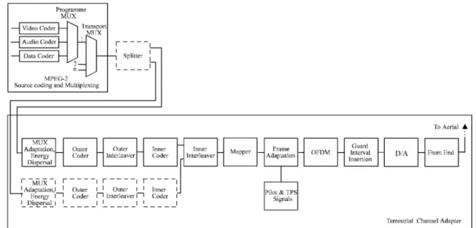
(13) into fractional acquisition and integral acquisition, respectively. In this thesis, we choose Digital Video Broadcasting-Terrestrial/Handheld (DVB-T/H) as the research topic because DVB-T/H is a narrow subcarrier spacing and continuous time reception OFDM system. These features will increase the difficulty of CFO synchronization. A low complexity CFO synchronization scheme for DVB-T/H system will be proposed in this thesis.. 1.2. Introduction to DVB-T/H system Digital Video Broadcasting-Terrestrial (DVB-T) has been subjected to technical. discussion for many years and undoubtedly been shown as a great success in delivering high quality digital television by terrestrial means [3]. DVB-T standard has been produced by European Telecommunication Standard Institute (ETSI) in Aug, 1997. It has been applied in many countries around the world such as Taiwan. Although the DVB-T reception can be applied in mobile environment, the ability of reception for handheld terminals is still not good enough because of its high operation power. Therefore, Digital Video Broadcasting-Handheld (DVB-H) was also proposed based on the DVB-T technology to provide broadcast services for handheld devices such as PDAs or mobile phones [7]. The detailed concepts of DVB-T and DVB-H will be illustrated later. The transmission system of the DVB-T standard is shown in Fig. 1.1. It contains the blocks for source coding, outer coding and interleaving, inner coding and interleaving, mapping, OFDM modulation, and frame adaptation, respectively. In the case of two-level hierarchy, the functional block diagram of the system must be expended to include the modules shown in dashed line. As we can see the source coding of audio and video signals is based on ISO-MPEG2 standard. After the MPEG2 transport multiplexer, a Reed-Solomon (RS) shortened code (204,188, t=8) and a convolutional byte-wise interleaving with depth I=12 shall be applied to generate error protected packets. As Fig. 1.1 shows, the outer 2.
(14) interleaver is followed by the inner coder. This coder is designed for a range of punctured convolutional codes, which allows code rates of 1/2, 2/3, 3/4, 5/6, and 7/8. If two-level hierarchical transmission is used, each of two parallel inner codes has its own code rate. Afterward, the inner interleaver is block based bit-wise interleaving. The constellation mapping for OFDM subcarriers operates with various modes after the inner interleaver. The constellation modes are QPSK, 16-QAM, 64-QAM, non-uniform 16-QAM, and non-uniform 64-QAM, respectively. The transmission channel bandwidth is 6MHz, 7MHz, and 8MHz, respectively.. Fig. 1.1 Functional Block diagram of DVB-T system The DVB-T system uses OFDM technique with various transmission parameters. The parameters for 8MHz channel bandwidth in DVB-T standard are listed in Table 1-1. Two modulation modes are defined: a 2k mode and an 8k mode. The 2k mode is suitable for short distance transmission and high speed mobile reception because of its short symbol duration and wide subcarrier spacing. On the contrary, the 8k mode is suitable for long distance transmission and deep multipath spread. Other parameters such as code arte, constellation mode, and guard interval length can also be decided properly according to the broadcasting channel condition of the local area. 3.
(15) Table 1-1 Parameters for 8MHz channel in DVB-T standard Parameter. 8k mode. 2k mode. Number of subcarriers K. 6817. 1705. Value of carrier number Kmin. 0. 0. Value of carrier number Kmax. 6816. 1704. FFT size N. 8192. 2048. Symbol duration TU. 896µs. 224µs. Subcarrier spacing 1/TU. 1.116KHz. 4.464KHz. Spacing between Kmin and Kmax. 7.61MHz. 7.61MHz. Guard interval Ng/N. 1/4,1/8,1/16,1/32. 1/4,1/8,1/16,1/32. An OFDM frame consists of 68 OFDM symbols and four frames constitute a super-frame. In addition to the transmitted data, an OFDM symbol contains several kinds of reference signals for synchronization and channel estimation such as scattered pilots, continual pilots, and TPS (Transmission Parameter Signaling) pilots. Scattered pilots are inserted every 12 subcarriers and have an interval of three subcarriers in the next adjacent symbol. Continual pilots locate at fixed subcarrier index which contain 177 for 8k mode and 45 for 2k mode, respectively. Both scattered pilots and continual pilots are transmitted at boosted power level of 16/9 whereas the data subcarriers are normalized to 1, and modulated according to the PRBS (Pseudo Random Binary Sequence) sequence (X11+X2+1). The TPS pilots are used for signaling parameters related to transmission scheme, i.e. to channel coding and modulation. The TPS pilots are defined over 68 consecutive OFDM symbols and transmitted in parallel on 17 TPS subcarriers for 2k mode and 68 for 8k mode. Each OFDM symbol conveys one TPS bit which is differentially encoded in every TPS subcarrier. The TPS information contains frame number, constellation, hierarchy, code rate, guard interval, FFT mode, and BCH error protection code, respectively. Unlike continual and scattered pilots, TPS. 4.
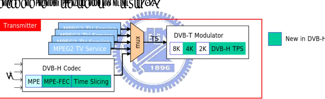
(16) pilots are transmitted as the normal power level of 1 with DBPSK modulation. The DVB-H technology is a spin-off of the DVB-T standard. It is large extent compatible to DVB-T but takes into account the specific properties of the addressed terminals- small, lightweight, portable, battery-powered devices in mobile environment. Unlike the DVB-T transport stream adopted from the MPEG2 standard, the DVB-H system is IP (Internet Protocol)-based, therefore the outer DVB-H interface is the IP interface. The IP data are embedded into the transport stream by means of the MPE (Multi Protocol Encapsulation) frame, an adaptation protocol defined in the DVB Data Broadcasting Specification [8]. One MPE frame contains one or more IP datagrams and has a maximum number of 1024 rows and a constant number of 255 columns. The block diagram of DVB-H. Transmitter. MPEG2 TV Service MPEG2 TV Service MPEG2 TV Service MPEG2 TV Service. mux. codec and transmitter is as shown in Fig. 1.2.. DVB-T Modulator. TS. New in DVB-H. 8K 4K 2K DVB-H TPS. DVB-H Codec. IP. MPE MPE-FEC Time Slicing. Fig. 1.2 Block diagram of DVB-H codec and transmitter As we can see the DVB-H codec is composed of the MPE, MPE-FEC, and time slicing. In order to satisfy the low power issue in battery-powered terminals, a time-multiplexed transmission of different service is exploited. This technique, called time slicing, allows for selective access to desired data and results in a large battery power saving effect. The burst duration of time slicing is in the range of several hundred ms whereas the off-time may amount to several seconds. The lead time for power-on and resynchronization is assumed to be less than 250ms. Depending on the duty/turn-off ratio, the resulting power saving may be more than 90%. For mobile channels reception and long delay spread conditions, an enhanced error protection scheme on the link layer is needed. This scheme is called MPE-FEC and 5.
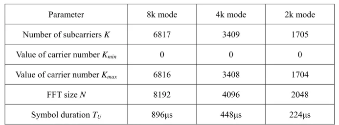
(17) employs powerful channel coding and time interleaving. The MPE-FEC scheme consists of an RS code in conjunction with an extensive block interleaving. The RS (255, 191, 64) code is utilized to perform MPE-FEC error protection. Besides, a virtual block interleaving effect is also performed by reading from and writing to the MPE frame in column direction whereas coding is applied in row direction. As for the physical layer, the DVB-H is compatible with the DVB-T standard except some additional points. First, the DVB-H provides new TPS pilots which exploit the reserved TPS subcarriers defined in the DVB-T standard. The new contents of the TPS pilots provide the information about MPE-FEC and time slicing. Besides, an additional OFDM transmission mode and a new symbol interleaving method within the inner interleaver, 4k mode and in-depth interleaving, are also provided by the new TPS pilots. DVB-H provides an intermediate 4k mode with 4096-point FFT in the OFDM modulation. The 4k mode represents a compromise solution between the 2k and 8k mode to satisfy long distance transmission and mobile reception. The in-depth interleaving allows the symbol interleaver operates at 8k interleaving length while the 2k or 4k mode is applied to improve the interleaving performance. Besides, the DVB-H also supports 5MHz transmission channel bandwidth. The parameters for 8MHz channel bandwidth in DVB-H standard are listed in Table 1-2. Table 1-2 Parameters for 8MHz channel in DVB-H standard Parameter. 8k mode. 4k mode. 2k mode. Number of subcarriers K. 6817. 3409. 1705. Value of carrier number Kmin. 0. 0. 0. Value of carrier number Kmax. 6816. 3408. 1704. FFT size N. 8192. 4096. 2048. Symbol duration TU. 896µs. 448µs. 224µs. 6.
(18) Subcarrier spacing 1/TU. 1.116KHz. 2.232KHz. 4.464KHz. Spacing between Kmin and Kmax. 7.61MHz. 7.61MHz. 7.61MHz. Guard interval Ng/N. 1.3. 1/4,1/8,1/16,1/32 1/4,1/8,1/16,1/32 1/4,1/8,1/16,1/32. Organization of This Thesis This thesis is organized as follows. In chapter 2, the signal models and the detailed. algorithms of the proposed CFO synchronization scheme will be introduced. The simulation result and performance analysis will be discussed in chapter 3. Chapter 4 will introduce the design methodology, hardware architecture, and the chip summary of the proposed design. Conclusion and future work will be given in chapter 5.. 7.
(19) Chapter 2 . Carrier Frequency Offset Synchronization Algorithms In this chapter, we introduce the signal model and the effect of carrier frequency offset (CFO) in DVB-T/H system first. The algorithms of CFO synchronization in different synchronization categories will be illustrated in later sections. Some comparison and discussion between developed and the proposed algorithms are also made.. 2.1. Introduction to Carrier Frequency Offset OFDM is a bandwidth efficient signal scheme for digital communications. In OFDM. systems, the spectrum of the individual subcarrier mutually overlaps and exhibits orthogonality to achieve optimum spectrum efficiency as shown in Fig. 2.1. 1. 0.8. 0.6. 0.4. 0.2. 0. -0.2. -0.4 -4. -3. -2. -1. 0. 1. 2. 3. 4. f(k) Fig. 2.1 Spectrum of five orthogonal subcarriers of OFDM systems 8.
(20) However, OFDM is very sensitive to the CFO introduced by the mismatch of oscillator frequency between transmitter and receiver. CFO causes linear phase error in time domain and shifts the subcarrier index in frequency domain, respectively. Once CFO exists, the orthogonality between subcarriers will be destroyed and the degradation of the system performance will be serious. Compared with other OFDM based system such as IEEE 802.11a, the subcarrier space of DVB-T/H system is relatively narrower and the tolerance of carrier frequency offset is also worse [3][5]. Hence the CFO synchronization is a very critical problem to be solved in DVB-T/H system.. 2.1.1. Signal Model of Carrier Frequency Offset. Consider an OFDM system using an inverse fast Fourier transform (IFFT) of size N for modulation. Each OFDM symbol is composed of K (K<N) data subcarriers al ,k , where l denotes the OFDM symbol index and k ( 0 ≤ k < K ) denotes the subcarrier index. After IFFT, a cyclic prefix composed of Ng samples is inserted to avoid the influence of multipath channel delay spread. So a transmitted symbol has Ns =N+ Ng samples with sample period T. The transmitted complex baseband signal of the l-th symbol can be expressed as. sl (t ) = e. j 2π tf c ,tx. ⎧⎪ 1 ⎨ ⎪⎩ N. K −1. ∑ al ,k ⋅ e. j 2π k '( t − ( N g + l ⋅ N s )T ) NT. k =0. ⎪⎫ ⎬ ⎪⎭. (2-1). where f c ,tx is the central frequency of the transmitter RF oscillator, and k ' is the subcarrier index relative to the centre frequency, k ' = k − ( K − 1) / 2 .. Since the CFO ∆f ( ∆f = f c ,tx − f c ,rx ) between transmitter and receiver RF oscillator can be expressed as a time-variant phase error, e j 2π∆ft , the l-th received symbol after sampling with period T’ at time instants tn=(lNs+Ng+n)T’ and removing guard interval can be expressed as. 9.
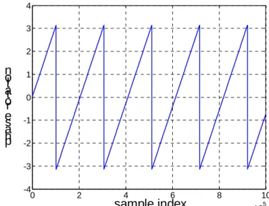
(21) rl (n) = e j 2π∆ftn ⋅ sl (tn ) ∗ h(tn ,τ ) + wl (n) =e. j 2π∆ftn. 1 ⋅ N. K −1. ∑a k =0. l ,k. ⋅e. j 2π k '( tn − ( N g + l ⋅ N s )T ) NT. ∗ h(tn ,τ ) + wl (n). (2-2). where h(tn ,τ ) is the channel impulse response with delay spread τ , wl (n) is the complex-valued additive white Gaussian noise (AWGN). After demodulation via a fast Fourier transform (FFT), the l-th OFDM symbol at subcarrier k, Rl ,k is as follows N −1. Rl ,k = ∑ rl (n)e − j 2π k ' n / N n =0. =e. j 2πε ( lN s + N g )(1+ζ ) / N. e. j. 2π k ' ( lN s + N g )ζ N. ⋅ α ⋅ H l ,k ⋅ al ,k + ICI l ,k + Wl ,k. (2-3). where ε = ∆fNT is the CFO value normalized with the subcarrier space, ζ is the sampling clock offset (SCO) ( ζ = (T '− T ) / T ), α is an attenuation factor which is close to 1, and. ICI l ,k is the inter-carrier interference noise due to carrier frequency offset. Likewise, H l ,k is the channel frequency response on the k-th subcarrier of the l-th OFDM symbol with the assumption that the channel is stationary within at last one symbol, Wl ,k is a zero-mean stationary complex process as well.. 2.1.2. Effect of Carrier Frequency Offset. As previous section shows, CFO introduces various imperfect effects to the received signal. From the viewpoint of time domain, the CFO can be expressed as a time-variant phase error. The rotated phase error is in proportion to the received sample time instants tn and can be expressed as. θl (n) = 2π∆ftn = 2πε (lN s + N g + n) / N. (2-4). where θ is the phase rotation caused by CFO. Unlike other packet-based communication systems such as IEEE 802.11a, DVB-T/H is a continuous-data transmission system and the 10.
(22) receiving of data continues until the receiver is turned off. So the phase error will still be large even in very weak CFO environment when the receiver operates for a long time as shown in Fig. 2.2. 4 3 2. n oi t at or e s a h p. 1 0 -1 -2 -3 -4 0. 2. 4. 6. 8. sample index. 10 5. x 10. Fig. 2.2 Phase rotation in time domain for long time reception when ε=0.01 1. 1. 0.8. 0.8. 0.6. 0.6. ICI 0.4. 0.4. 0.2. 0.2. 0. 0. -0.2. -0.4 -4. ICI. -0.2. -3. -2. -1. 0. 1. 2. 3. 4. -0.4 -4. f (k). -3. -2. -1. 0. 1. 2. 3. 4. f(k). (a) ε=0.1. (b) ε=1.1. Fig. 2.3 Spectrum of five subacrriers in carrier frequency offset environment CFO results in different effects in frequency domain. It not only reduces the amplitude but also shifts the phase of the demodulated signal. Further more, the second term of (2-3). ICI l ,k degrades the system performance strongly because it destroys the orthogonality within each subcarrier in OFDM symbols, and can be expressed as. 11.
(23) sin(πε ). K −1. ICI l ,k = ∑ H l ,k al ,k ~. k =0 ~. ~. N sin(π (k − k + ε ) / N ). ~. ⋅ e jπε ( N −1) / N e − jπ ( k − k ) / N .. (2-5). k ≠k. Because the subcarrier space of DVB-T/H system is very narrow (about 0.7~4.5 KHz), we can divide the normalized CFO value into integral part and fractional part, and can be expressed ass. ε = εI + εF. (2-6). From Fig. 2.3, we can find that CFO causes inter-carrier interference noise within each subcarrier and makes the orthogonality of spectrum lost. Once the integral part of CFO ε I is not zero, all of the subcarriers will shift circularly. The shift of subcarrier index will make the channel estimator receive wrong pilot sequence at the pre-defined pilot index and then the calculated channel frequency response will be not reliable. Also the TPS decoder can not receive correct TPS pattern to decode the correct system parameter. All of these imperfect effects in different domain should be corrected by the aid of CFO synchronization to obtain good receiving performance.. 2.2. Carrier Frequency Offset Synchronization Scheme From previous section, we can know that the imperfect effects caused by CFO degrade. the system performance enormously. Besides, the DVB-T/H system is very sensitive to the CFO because of its narrow subcarrier space and continuous-data transmission scheme. So the synchronization of CFO is a very important factor and must be handled carefully. In our system platform, the CFO synchronization is divided into acquisition stage and tracking stage. As the beginning of receiving data, the acquisition stage estimates the CFO value roughly with the first 3 received symbols. After acquisition stage finishes, the integral CFO value and most of the fractional CFO value. ^. ε. F. ^. ε. I. should be estimated and compensated. The. 12.
(24) ^. tracking stage then turned on to track the residual fractional CFO value ε R ( ε F = ε F + ε R ) left by the acquisition stage until the receiver is turned off. The objective of CFO synchronization is to establish subcarrier orthogonality as fast and accurately as possible (acquisition) and then maintain orthogonality as well as possible at all times during online reception (tracking). However, a CFO acquisition algorithm alone can not be both fast and sufficiently accurate, because 1. Pre-FFT algorithms allow only fast acquisition of the fractional CFO but no acquisition of the integral CFO. 2. Post-FFT algorithms allow fast acquisition of the integral CFO but, due to lack of orthogonality, acquisition of fractional CFO is very complicate. Both fast and accurate acquisition can be attained by adopting a multi-stage synchronization strategy with two one-shot acquisition stages (one pre-FFT and the other post-FFT) followed by tracking. In DVB-T/H system, the data format provides for training is only for frequency domain (continual and scattered pilots) but not for time domain. Hence, pre-FFT non-data-aided acquisition and post-FFT data-aided acquisition and tracking algorithms are suitable. This leads to the overall CFO synchronization and compensation scheme as shown in Fig. 2.4.. CFO Compensator. from ADC. Pre-FFT CFO Acquisition (ε ^ ) F. ^. ε. F. εR. +. Post-FFTCFO Tracking (ε R ). ^. ε. to EQ. FFT. I. Post-FFT CFO Acquisition (ε I ). data CFO. Fig. 2.4 Overall CFO synchronization and compensation scheme The control loops of the three-stage synchronization subsystem operate in a 13.
(25) per-OFDM-symbol basis. When the CFO acquisition or tracking stage has generated an estimation of CFO value, the CFO compensator will calculate the effective compensation value before the beginning of the next pre-FFT OFDM symbol, and then start to compensate the updated CFO value when the next pre-FFT OFDM symbol comes.. 2.3. Fractional Carrier Frequency Offset Synchronization The estimation of fractional CFO was first proposed by Moose in 1994 [9]. This. approach utilizes maximum likelihood estimation (MLE) of differential phase between two repeated training symbols in frequency domain to estimate the fractional CFO value. The estimation range is limited within ±0.5 subcarrier space, and can be expressed as ^. ε. F. K / 2 −1 ⎡ ⎤ Im R1,* k ⋅ R2,k ⎥ ∑ ⎢ 1 ⎥ = tan −1 ⎢ kK=−/ 2K−/12 2π * ⎢ Re R1,k ⋅ R2,k ⎥ ⎢⎣ k =−∑ ⎥⎦ K /2. (2-7). * where R1,k and R2,k are the pre-defined training symbols in frequency domain.. In WLAN IEEE 802.11a system, similar idea is exploited but different training patterns are utilized [10]. The estimation of CFO is accomplished by the aid of pre-defined short preamble and long preamble in time domain and achieves wider estimation range than Moose’s approach. However, there is no any pre-defined training sequence except the continual and scattered pilots in DVB-T/H system. The former two data-aided algorithms are both not suitable solutions for our application. From section 2.1.2, we can know that the phase of the received signal in time domain is rotated by CFO linearly according to the sample time instant tn as (2-4) shows. When the difference of sample time instant between two received signals is equal to FFT length N, the phase error difference caused by CFO between them can be expressed as. θl (n + N ) − θl (n) = 2π∆ftn + N − 2π∆ftn 14.
(26) = 2πε (lN s + N g + n + N ) / N − 2πε (lN s + N g + n) / N = 2πε = 2π (ε I + ε F ) .. (2-8). Since the phase rotation of multiples of 2π can be ignored, the phase error between rl (n) and rl (n + N ) is just equal to 2πε F and in proportion to the fractional CFO value. This phase error feature will be utilized in our proposed fractional CFO synchronization. In the proposed DVB-T/H system platform, however, no any useful training symbol can be used in time domain. So if we want to exploit the phase error feature between rl (n) and rl (n + N ) , the guard interval based algorithm is the most suitable solution. In order to prevent the influence of multipath channel spread and inter-symbol interference (ISI), a cyclical prefix is inserted in front of each symbol. The cyclical prefix must be composed of partial signal in the back of the symbol, and its length has to be longer or equal to the multipath delay spread as shown in Fig. 2.5. channel impulse response. GI(Ng). Symbol (N) copy. Fig. 2.5 Guard interval insertion and multipath channel spread Because all the samples in guard interval are copied from the rear part of the symbol, the received sample rl (n) in guard interval and rl (n + N ) in the symbol’s tail are exactly identical when there is no any distortion exists such as multipath delay spread or CFO. As previous sections mentioned, the difference of rotated phase error between rl (n) and rl (n + N ) is in proportion to the fractional CFO value ε F . We can conclude that the tail received sample and its cyclical prefix show the same property except for a phase rotation error which is exactly 2πε F . The estimation of fractional CFO value can be accomplished with the MLE of differential phase between guard interval and the tail of symbol [11], and can 15.
(27) be expressed as N s −1. x=. ∑. n= Ns − N g. =e. j 2πε F. rl*,n − N ⋅ rl ,n = N s −1. ∑. n= Ns − N g. ^. ε. F. rl ,n − N. N s −1. ∑. n= Ns − N g. (rl*,n − N ⋅ rl ,n − N )e j 2πε F. 2. N s −1 ⎡ ⎤ Im rl*,n − N ⋅ rl ,n ⎥ ∑ ⎢ 1 1 n= Ns − N g ⎥ = arg( x) = tan −1 ⎢ N s −1 ⎢ ⎥ 2π 2π * ⎢ Re ∑ rl ,n − N ⋅ rl ,n ⎥ ⎢⎣ n = N s − N g ⎥⎦. (2-9). (2-9) shows that the distinguishable phase error of arg( x) is within ±π , so the estimation range of the fractional CFO synchronization is also limited within ±0.5 subcarrier space. In the proposed CFO synchronization scheme, the rough estimation of fractional CFO is calculated with the first symbol after symbol boundary is decided. And then the estimated fractional CFO value. ^. ε. F. will be sent to the CFO compensator before data being sent to FFT. demodulator as Fig. 2.4 shows. If AWGN is the only external distortion, the accuracy of the fractional CFO synchronization will be very excellent because the correlation of guard interval and tail of symbol can average the noise induced by AWGN. However, the DVB-T/H system is an outdoor wireless communication application and robust ability to long delay spread of multipath channel is necessary. As Fig. 2.5 shows, the delay spread of multipath channel will affect the data of the front portion of the guard interval directly especially when the length of guard interval is relatively short (2k mode, N g / N = 1/ 32 ). In order to reduce the effect of multipath delay spread, several beginning samples of the guard interval must be discarded, and (2-9) can be rewritten as. 16.
(28) ^. ε. F. N s −1 ⎡ ⎤ * ⎢ Im ∑ rl ,n − N ⋅ rl ,n ⎥ 1 1 n= Ns − N g + y ⎥ arg( x) = tan −1 ⎢ = N s −1 ⎢ ⎥ 2π 2π * ⎢ Re ∑ rl ,n − N ⋅ rl ,n ⎥ ⎣⎢ n = N s − N g + y ⎦⎥. (2-10). where y is the number of discarded samples. However, discarding too many samples will also degrade the averaging performance. The optimal value of y will be shown by simulation result in chapter 3.. 2.4. Integral Carrier Frequency Offset Synchronization From previous section, we can know that the time domain guard interval correlation. algorithm can only deal with the rotated phase error caused by the fractional CFO value. The imperfect effect caused by the integral CFO should be monitored and synchronized in frequency domain. Thanks to the compensation of. ^. ε. F. , the residual fractional CFO ε R is. relatively smaller ( ε R ≤ 0.02 ) and the ICI noise is also neglected. In essence, the k-th transmitted subcarrier shows up at FFT output bin with subcarrier index k + ε I as Fig. 2-3 (b) shows. The subcarrier index shift, which is just equal to the integral CFO ε I , must now be detected by using the pre-defined training sequence (continual and scattered pilots) or the null subcarriers. In later sections, some different algorithms of integral CFO synchronization will be illustrated and discussed.. 2.4.1. Conventional Pilots Based Approach. The DVB-T/H standard defines continual and scattered pilots for synchronization and equalization in frequency domain [3]. The signal power of the two kinds of pilots is at boosted power level and larger than the data and null subcarriers. The only difference between continual and scatter piloted is their subcarrier index. The continual pilots locate at fixed subcarrier index and do not shift as OFDM symbol number increases. However, scattered 17.
(29) pilots are inserted every 12 subcarriers and have an interval of 3 subcarriers in the next adjacent symbol. In general, the continual pilots based integral CFO synchronization algorithms are the most widely used because of its good performance in low SNR and mobile environment [12][13]. The main idea of this approach is based on the MLE theory. In the first step, the correlation between two continual pilots at the same subcarrier index for two successive symbols in the frequency domain based on shifting the pilot positions is calculated, and can be expressed as. Ci =. ∑R. * l −1, k. k = Pi. ⋅ Rl ,k , i ≤ m. (2-11). where Ci is the correlation value at the i-th shift location, Pi =[ p1 + m, p2 + m,..., pP + m, ] are the positions of the subcarriers to be correlated in two successive symbols, and m is the estimation range. The integer CFO value ε I is then estimated by detecting the offset position i where the value Ci is maximized as ^. ε. I. = m ax ( C i ). (2-12). i. correlation. (j-1)-th symbol. j-th symbol. .... …… 47. .... 48. 49. 48. 49. … …… …. 53 54. 55. 54. 55. ……. 47. ……… … 53. …. 88 87. 89. 88 87. …. +. +. + …. …. C−1. C0. C1 …. 89. subcarrier index. … subcarrier index. continual pilot data. MAX: estimated CFO=1. Fig. 2.6 Received signal in frequency domain when CFO=1 subcarrier space 18.
(30) Fig. 2.6 shows the received signal according to the subcarrier in frequency domain when the integral CFO is equal to 1 subcarrier space. In DVB-T/H 2k mode, the positions of continual pilots should be 0, 48, 54, 87…. Accordingly, if the maximum value of Ci is obtained from subcarriers 1, 49, 55, 88…, the estimated integral CFO is 1 because the position of maximum correlation is achieved one subcarrier position away from the original continual pilots. Because the continual pilots are transmitted at boosted power level, the power difference of correlation values is still apparent and not affected by strong noise even in low SNR and deep delay spread channel condition. The total number of multiplication when the acquisition of integral CFO is finished can be expressed as M = (2m + 1) ⋅ ( P ⋅ 4 + 2). (2-13). where M is the total number of multiplication, and P is the number of correlated pilots, respectively. In DVB-T/H system, P is 45, 89, and 177 for 2k, 4k, and 8k mode. Apply (2-13) we can see that as the search range increases, if all of the continual pilots are used for estimation, the total number of multiplication will increase enormously. For example, if the desired search range m is 60 for 2k mode when using all continual pilots, the number of multiplication will raise up to 22022. For low power consideration, such large number of multiplication should be avoided. The tradeoff between estimator performance and power consumption has become an important task for the integral CFO acquisition. Besides the continual pilots based approach, another algorithm based on both continual and scattered pilots (CP+SP) was also proposed [14]. This algorithm calculates the correlation between possible 4 types of CP+SP patterns with the shifted received symbol in frequency domain. By detecting the peak value of the correlation result among the 4 CP+SP patterns, the integral CFO and the scattered pilot mode can be estimated at the same time, and can be expressed as ^. ε. I. = max i. P'. ∑R k =1. l , z ,k +i. ⋅ Yz*,k , z ∈ [0,1, 2,3]. 19. (2-14).
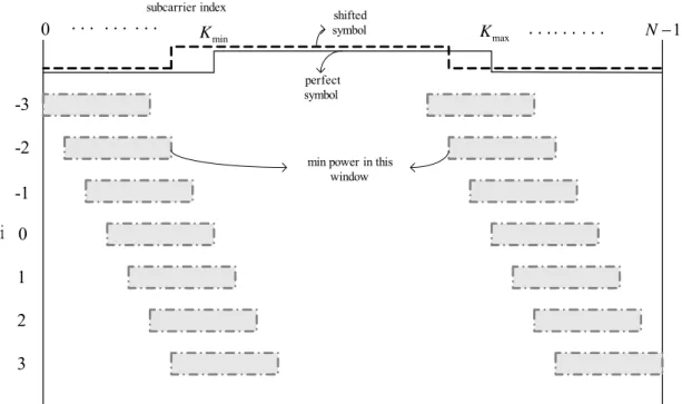
(31) where P’ is the total number of CP+SP, Yz ,k is the z type CP+SP sequence, and z is the subcarrier index pattern of 4 possible types of CP+SP, respectively. Although this approach can acquire the scattered pilot mode and the integral CFO at the same time, the computational complexity also rises to about 4 times of the continual pilots based one and leads to more power consumption.. 2.4.2. Conventional Guard Band Based Approach. In DVB-T/H system, the number of subcarriers K within an OFDM symbol is chosen smaller than the symbol length N to provide that so-called “guard bands” at the edges of the transmission spectrum are left free. Hence all the subcarriers within guard-bands are composed of null subcarriers and the transmitted signal power is zero. According to the DVB-T standard, the signal power of the useful data subcarrier is normalized to 1, and the power of the reference pilots is 16/9 [3]. By exploiting the feature of power difference, a guard band power detection based algorithm for integral CFO acquisition was proposed by Kim in 1997 [15]. This algorithm utilizes the guard bands in both sides of spectrum as a moving window to search the subcarrier index shift value caused by the integral CFO. The main idea is that when the useful signal component (data or pilot subcarriers) is not within the moving window, the total component power within the moving window includes only noise component. So when the power of the moving window reaches minimum, the shift value of the window is equal to the shift value of signal spectrum due to the integral CFO, and can be expressed as ^. ε. I. = min{ i. K min −1. ∑. k = K min − w. K max +1. 2. Rl ,k +i +. ∑. k = K max + w. 2. Rl ,k +i }, i ≤ m. (2-15). where w is the width of the moving window at both sides of the guard band and is set as 5.. 20.
(32) subcarrier index. 0. ... ... .... K min. shifted symbol. K max. . . .. . . . . .. N −1. perfect symbol. -3 -2. min power in this window. -1 i 0 1 2 3. Fig. 2.7 Received symbol in frequency domain when CFO is -2 Fig. 2.7 shows the received symbol spectrum in frequency domain according to subcarrier index when the integral CFO is -2 subcarrier space. As we can see the minimum power appears in the moving window where i is -2 because it does not include any data or pilot component. The total number of multiplication M required for the acquisition of integral CFO can be expressed as M = ( w + 2m) ⋅ 4. (2-16). From (2-16), we can find that the number of multiplication M could be reduced effectively by using small moving window width w. However, small w may lead this algorithm to worse performance in low SNR and deep frequency selective fading environment. So the trade-off between w and M should be treated very carefully. In order to improve the performance of the conventional guard band power detection based algorithm, another modified guard band power detection method was proposed [16]. This algorithm modifies the structure of the symbol spectrum and inserts additional null subcarriers within the useful subcarriers to reduce the influence from ICI noise and deep frequency selective fading. However, the modification conflicts with the DVB-T/H standard 21.
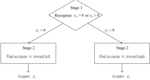
(33) and can not be applied for our system platform.. 2.4.3. Proposed 2-stage Approach. From previous sections, we can conclude that neither the continual pilots based algorithm nor the guard band power detection based algorithm can satisfy good performance and low computational complexity at the same time. Besides, the number of multiplication of all these algorithms is in proportion to the search range. If we want to let the integral CFO estimator work in low SNR and deep frequency selective fading environment and search large range CFO with low computational complexity, none of these algorithms is the best choice. In order to solve this problem, a 2-stage integral CFO acquisition algorithm is proposed as Fug 2.8 shows. The objective of the first stage is to recognize whether the integral CFO value ε I is positive or negative (i.e. to find whether the direction of subcarrier shift due to integral CFO is right or left) with a low complexity guard band based algorithm. Once the first stage finishes and finds the direction of the subcarrier shift, the search range and the number of multiplication can be reduced half at the same time. In the second stage, the accurate integral CFO value ε I will be acquired along the direction estimated by the first stage with the proposed continual pilots based algorithm or guard band based algorithm. The detailed content of the proposed 2-stage approach will be illustrated in later sections. Stage 1 Recognize ε I > 0 or ε I < 0. εI < 0. εI > 0. Stage 2. Stage 2. Find accurate ε I toward left. Find accurate ε I toward right. Acquire ε I. Acquire ε I. Fig. 2.8 Proposed 2-stage integral CFO algorithm scheme 22.
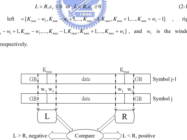
(34) 2.4.4. The First Stage of the Proposed Approach. The main task of this stage is to find whether the integral CFO value ε I is positive or negative fast and efficiently, so a left window and a right window that composed of w1 guard band null subcarriers and w1 data subcarriers at the boundary between guard band and data are exploited. In the first step, the summation of signal power of two successive OFDM symbols based on the position of left and right window is calculated separately. Once the integral CFO value ε I is not equal to zero, the subcarrier distribution of guard band and data within the left and right window will be imbalanced. So in the second step, we compare the calculated correlation power to decide whether the integral CFO value ε I is positive or negative, and can be expressed as L=. ∑ ⎡⎣⎢ R. k =left. R=. l −1, k. 2. 2 + Rl ,k ⎤⎥ ⎦. 2 2 ⎡R ⎤ R + − l 1, k l , k ⎥⎦ ⎣⎢ k = right. ∑. L > R, ε I ≤ 0 or L < R, ε I ≥ 0 where. left. (2-17). = [ K min − w1 , K min − w1 + 1,..., K min − 1, K min , K min + 1,..., K min + w1 − 1]. ,. right. = [ K max − w1 + 1, K max − w1 ,..., K max − 1, K max , K max + 1,..., K max + w1 ] , and w1 is the window width, respectively.. Kmin. Kmax data. GB w1 w1. L L > R, negative. Symbol j-1. GB. Symbol j. w1 w1 data. GB. GB. R Compare. L < R, positive. Fig. 2.9 The first stage of the proposed integral CFO estimator 23.
(35) As shown in Fig. 2.9, we can see that if the integral CFO value ε I is larger than zero, the received subcarrier will shift toward right and the number of guard band signal will be more than that of the data signal in the left window. Also in the right window, the number of the guard band signal will be less than that of the data signal. The power difference between the left and right window will appear and help us to decide whether the integral CFO value. ε I is positive or negative. The total number of multiplication of the first stage can be expressed as M = 8 ⋅ w1. (2-18). From (2-18) we can know that the number of multiplication of the first stage is not affected by the estimation range m and low complexity calculation can be achieved by choosing smaller window width. However, too small window width will affect the performance of the first stage. The optimal window width will be shown by simulation result in chapter 3.. 2.4.5. The Second Stage of the Proposed Approach. By the aid of the first stage, the search range of the second stage can be reduced from ± m to m . However, the result of the first stage may be incorrect while the integral CFO value ε I is smaller than the window width w1 in deep frequency selective fading channel environment. In order to prevent estimation error, the search range should be extended from m to m + w1 , implying that we should add more w1 points to the search range toward the reverse direction to assure correct acquisition result when the integral CFO value ε I is near zero in deep frequency selective fading channel. Once the search range of the second stage is decided, there are still various algorithms can be applied for acquisition the accurate integral CFO value ε I . The trade-off between estimator performance and computational complexity, however, still exists among the previous mentioned algorithms. Considering acceptable acquisition performance and efficient 24.
(36) computation load, a reduced continual pilot based algorithm and a guard band power detection based algorithm are proposed for the acquisition in the second stage, and will be illustrated in later sections.. (1) Proposed Reduced Continual Pilot Based Approach From (2-13), we can find that the number of multiplication of the conventional continual pilot based approach is in proportion to not only the search range m but also the number of utilized continual pilot P. In order to achieve efficient computational load, the number of utilized continual pilot should be reduced with the search range at the same time. Hence a reduced continual pilot based approach is proposed. The main feature of the proposed reduced continual pilot based algorithm for the second stage integral CFO acquisition is similar to the conventional continual pilot based one. But the proposed one exploits only a part of the continual pilot instead of all of them to reduced the number of multiplication, and can be expressed as ^. ε. I. = max i. ∑R. k = Pr ,i. * l −1, k. ⋅ Rl ,k. (2-19). where Pr ,i is the shifted subcarrier index of the selected continual pilots, − m ≤ i ≤ w1 while negative value estimated by the first stage, and − w1 ≤ i ≤ m while positive value, respectively. The number of multiplication for the proposed reduced continual pilot approach can be expressed as. M = (m + w1 + 1) ⋅ ( Pr ⋅ 4 + 2). (2-20). where Pr is the total number of the correlated continual pilots. Because the power difference between pilot and data subcarrier is very significant, it is not necessary to use all of the continual pilots and the acquisition performance is still acceptable to meet lower computational load. As (2-20) shows, the number of multiplication can be reduced effectively. 25.
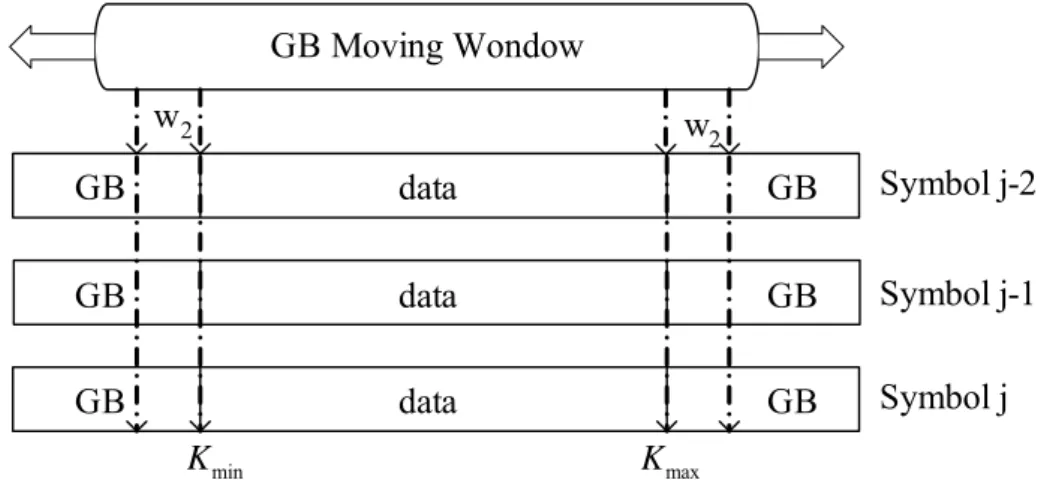
(37) The optimal value of the number of the selected continual pilots will be chosen by simulation and shown in chapter 3.. (2) Proposed Guard Band Power Detection Based Approach As previous sections mentioned, the conventional guard band power detection based algorithm requires fewer number of multiplication and performs worse performance in low SNR and deep frequency selectively fading environment because it utilizes only one OFDM symbol. In order to utilize the advantage of lower computational complexity and to improve the performance in critical channel condition, we propose a new guard band power detection based algorithm. By the aid of the proposed first stage, the search range of the second stage can be reduced effectively and more OFDM symbols can be utilized to improve the acquisition performance. Thus the proposed guard band power detection based algorithm still keeps the moving window scheme and calculates the summation of signal power within three successive OFDM symbols, and can be expressed as ^. ε. I. i. K max +1. K min −1. 2 2 2 2 2 2 ⎡R ⎤+ ⎡R ⎤} R R R R + + + + ∑ ∑ l , k + i l − 1, k + i l − 2, k + i l , k + i l − 1, k + i l − 2, k + i ⎢ ⎥ ⎢ ⎣ ⎦ ⎣ ⎦⎥ k = K min − w2 k = K max + w2. = min{. (2-21) where w2 is the width of the moving window at both sides of the guard band, − m ≤ i ≤ w1 while negative value estimated by the first stage, and − w1 ≤ i ≤ m while positive value, respectively. As Fig. 2.10 shows, by the use of summation within three successive OFDM symbols, the distortion induced by noise in severe environment can be decreased effectively. The number of multiplication can be expressed as. M = ( w2 + m + w1 ) ⋅12. (2-22). Compared (2-22) with (2-16), we can see that the total number of multiplication of the proposed guard band power detection based approach consumes about 1.5 times of that of the conventional approach. However, the acquisition performance is improved significantly. The 26.
(38) detailed performance simulation and comparison will be illustrated in chapter 3. GB Moving Wondow w2. w2. GB. data. GB. Symbol j-2. GB. data. GB. Symbol j-1. GB. data. GB. Symbol j. K min. K max. Fig. 2.10 The proposed guard band power detection based approach. 2.5. Residual Carrier Frequency Offset Synchronization After the acquisition stage estimates the integral and most of the fractional CFO value,. the residual CFO value is usually less than 1 to 2 percent of the subcarrier space. However, the phase error induced by such small value of CFO in time domain still affects the system performance for long time receiving operation. As Fig. 2.2 shows, the accumulative phase error when residual CFO value is 0.01 still exceeds π while the received number of data is more than 10,000. Besides, the Doppler effect in mobile environment also introduces small drift to CFO. Therefore the tracking of residual CFO is necessary and has to operate continuously until the reception is turned off. Generally speaking, the residual CFO value ε R is usually very small. Thus only fractional CFO estimation is sufficient. In particular, the estimation of the residual CFO at tracking stage requires precise and low variation result. Therefore in our DVB-T/H system platform, the tracking stage of CFO is divided into two parts. The first part estimates the residual CFO value symbol by symbol followed by a PI (proportional-integral) loop filter to reduce the variation. The tracking loop of the CFO synchronization is shown in Fig. 2.11.. 27.
(39) from ε ADC. e2 CFO Compensator. ^. ~ ^. e1. ^. ε +ε I. F. e1. FFT. PI loop filter. to EQ. One-shot residual CFO estimator. e1. data CFO. Fig. 2.11 The tracking loop of the CFO synchronization As shown in Fig. 2.11, e1 is the residual CFO value of the first iteration of the tracking ^. loop. After the estimation of e1 , the output of the residual CFO estimator e1 will be post-processed by the PI loop filter. When the second iteration starts, the CFO compensator will compensate the incoming data with the updated CFO value. ^. ε. ^. I. ~. + ε F + e1 and then get. the next residual CFO error e2 of the second iteration. As the CFO tracking loop works iteratively, the residual CFO error will be minimized.. 2.5.1. Residual CFO Estimation. The objective of the residual CFO estimator is to estimate the residual CFO error value precisely and fast. As previous section mentioned, only fractional CFO synchronization is sufficient for this estimator. Considering hardware integration and resource reuse, the fractional CFO estimator described in section 2.3 may can be utilized for the residual CFO estimator. However, the non-data-aided algorithm that exploits the guard interval is very sensitive to the inter-symbol interference introduced by the multipath delay spread and the estimated result may be not precise enough for the residual CFO estimation in deep delay fading environment. Only roughly fractional CFO value can be obtained with this approach. Therefore an efficient data-aided algorithm that employs the pre-defined continual pilots is 28.
(40) applied for the residual CFO estimator. After most of the CFO value is estimated and compensated, the residual CFO value is usually less than 1 to 2 percent of the subcarrier space and the ICI noise is small enough to be neglected. As (2-3) shows, regardless of the ICI term, the phase error caused by the residual CFO error and SCO at the k-th subcarrier of the l-th OFDM symbol in frequency domain can be expressed as. ϕl (k ) = 2πε R (lN s + N g )(1 + ζ ) / N +. 2π k (lN s + N g )ζ + φl (k ) N. (2-23). where φl (k ) is the phase of the channel frequency response H l ,k . If the channel is a slowly fading channel ( φl (k ) ≈ φl −1 (k ) ), the difference of phase rotation between two successive OFDM symbols is represented as. ϕ 'l (k ) = ϕl (k ) − ϕl −1 (k ). The second term. =. 2πε R N s 2πε R N sζ 2π kN sζ + + N N N. ≈. 2πε R N s 2π kN sζ + N N. (2-24). 2πε R N sζ can be ignored since the product of ε R ⋅ ζ is usually less than N. 2.0x10⁻⁶. From (2-24) we can know that the residual CFO ε R causes mean phase error and the SCO ζ causes linear phase offset between two consecutive OFDM symbols. If we take two adjacent continual pilots of arbitrary two consecutively received OFDM symbols, the phase rotation is shown in Fig. 2.12 [17]. The total phase rotation includes the effects of symbol timing offset, residual CFO and SCO. As we can see from Fig. 2.12, the magnitude of phase rotation induced by symbol timing offset is identical and in proportion to the subcarrier index among the two symbols. However, in the current symbol, the effect of residual CFO and SCO are accumulated in the phase of the previous symbol, where the residual CFO induces mean phase and SCO generates linear phase. Thus, we must estimate the residual CFO as well as the SCO by computing the phase rotation between two successive symbols. 29.
(41) Adjacent Continual Pilot. Sampling clock offset Previous symbol. CFO. Current symbol Symbol timing offset. subcarrier index. Fig. 2.12 Phase rotation between two successive OFDM symbols Since the phase error caused by residual CFO is identical within one OFDM symbol, the continual pilots which have fixed subcarrier index are exploited to estimate the residual CFO. In general, the residual CFO and the SCO are estimated jointly because their effects of phase rotation are uncorrelated. Thus a joint residual CFO and SCO estimation algorithm is applied as ^. ε. R ^. =. ζ =. 1 1 ⋅ ⋅ (ϕ 2,l + ϕ1,l ) 2π (1 + N g / N ) 2 1 1 ⋅ ⋅ (ϕ2,l + ϕ1,l ) 2π (1 + N g / N ) K / 2. ϕ1|2,l = arg[ ∑ Rl ,k ⋅ Rl*−1,k ]. (2-25). k∈C1|2. where C1 denotes the subcarrier index set of continual pilots which locates in the left half ( k ∈ [0, ( K − 1) / 2) ), and C2 denotes the subcarrier index set of continual pilots which locates in the right half ( k ∈ (( K − 1) / 2, K max ] ) of the OFDM symbol spectrum, respectively. Applying correlation of continual pilots within two successive OFDM symbols and accumulating the correlation results in two parts lead to the so-called CFD/SFD (carrier frequency detector / sampling frequency detector) algorithm [18]. The summation of ϕ2,l and ϕ1,l can compute mean phase error while subtraction of ϕ2,l and ϕ1,l produces the 30.
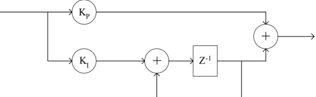
(42) linear phase error. As a result, the residual CFO and SCO can be estimated jointly by multiplying different coefficients. Besides the continual pilots based approach, some other scattered pilots based approaches are also presented in [14] and [19]. [14] proposes a residual CFO estimator that exploits the continual and scattered pilots between the l-th and the (l-4)-th OFDM symbol. The equation of this approach is very similar to (2-25) except the correlated symbols and pilots. The main feature of this algorithm is to use more pilots to reduce the distortion caused by AWGN and ICI noise. However, the convergence speed is extended about 2.5 times longer than that of the CFD/SFD algorithm because it utilizes the l-th and the (l-4)-th OFDM symbol. In [19], the residual CFO estimator exploits the scattered pilots within two successive OFDM symbols and has similar equation with (2-25). However, the subcarrier index of scattered pilots of two successive OFDM symbols is not identical and has a difference of 3. The estimated phase error between two scattered pilots is also distorted by the symbol timing offset. However, the symbol timing offset is an unknown factor and can not be estimated precisely by symbol synchronizer. So the estimation result of this approach is not reliable only if precise symbol offset value is estimated.. 2.5.2. Residual CFO Tracking Loop Filter. In order to reduce the variation of the estimated residual CFO, a PI loop filter is utilized in our CFO synchronization design [20]. The PI loop filter is composed of two paths. The proportional path multiplies the estimated residual CFO by a proportional factor K P . The integral path multiplies the estimated residual CFO by an integral factor K I and then integrates the scaled value by using an adder and a delay element. The block diagram of the PI loop filter is shown as Fig. 2.13.. 31.
(43) KP. + +. KI. Z-1. Fig. 2.13 Block diagram of PI loop filter The transform function of the PI loop filter can be represented as H ( z) = K P + K I. Z −1 1 − Z −1. (2-26). For small loop delay and K I − K P � K P � 1 , the standard deviation of the steady-state tracking error is expressed as. σ (e ') = K P / 2 ⋅ σ (e). (2-27). where e is the estimation error of the residual CFO estimator and e’ is the steady-state tracking error. The close-loop tracking time constant is approximately given by Tloop ≈ 1/ K P. (2-28). So from (2-27) and (2-28) we can find that there is a tradeoff between steady-state tracking error and tracking convergence speed. In our proposed DVB-T/H platform, the loop parameter KP is chosen as a larger value to increase the convergence speed in the beginning of tracking, and then switched to a smaller value to reduce the steady-state tracking error variation.. 32.
(44) Chapter 3 . Simulation and Performance Analysis In this chapter, the overall simulation platform built for DVB-T/H system will be illustrated first. The channel model and some other distortion source such as Doppler delay spread and SCO model will be discussed later. Finally, the performance analysis of the proposed CFO synchronization scheme and comparison with state of the art will be performed.. 3.1. Simulation Platform In order to verify the performance of the proposed CFO synchronization scheme, a. complete DVB-T/H baseband simulation platform is constructed in Matlab. The block diagram of the overall simulation platform is shown as Fig. 3.1.. IP Datagram. MPEG2 stream. DVB-H Codec. Scrambler. Outer Interleaver. Outer Coder. AWGN. Resampler. MPEG2 stream. IP Datagram. Pre-FFT Synchronization. De-scrambler. Inner Interleaver (in-depth, native). Inner Coder. SCO. FFT Window. Outer Decoder (RS Code). CFO. FFT (2k, 4k, 8k). Mapping. Doppler. Multipath. Post-FFT Synchronization. Channel Estimation. Outer De-interleaver. Inner Decoder (Viterbi Code). BER Measurement 2x10⁻⁴. DVB-H Codec. Fig. 3.1 Overall DVB-T/H platform 33. TPS & Pilot Insertion. IFFT (2k, 4k ,8k). GI Insertion. Pulse Shaping Filter. TPS Extraction. Inner De-interleaver (in-depth, native). Pilot Remove. De-mapping (Soft Decision). Equalization.
(45) As shown in Fig. 3.1, the blocks with dotted line is the specific function blocks for DVB-H system. By adding support of 4k IFFT/FFT, in-depth interleaving, and additional TPS information, the developed DVB-T system platform can share most of the function blocks with DVB-H system at the same time. The platform is composed of transmitter, channel, and receiver. A typical transmitter that receives data from MPEG2 encoder or IP datagram is completely established. The transmitter consist the full function of FEC blocks and OFDM modulation blocks. The coding rate, interleaving mode, constellation mapping mode, IFFT length, and guard-interval length are all parameterized and able to be selected while simulation. An oversampling and pulse shaping filter is added before data entering channel to simulate discrete signal as far as continuously. The oversampling rate is also parameterized and can be chosen according to the simulation accuracy. The roll-off factor of the pulse-shaping filter is chosen as a normal value α = 0.15 because it is not defined in the DVB-T/H standard. Various distortion models are adopted in the channel model to simulate real mobile environment such as multipath fading, Doppler spread, AWGN, CFO, and SCO. In practically, there are still some imperfect effects which contain co-channel interference, adjacent-channel interference, phase noise, and common phase error caused by imperfect front-end receiving. However, the distortion of these imperfect effects is relatively smaller compared with effective time-varying channel response caused by Doppler spread, CFO, and SCO. Therefore these effects are neglected in our simulation platform.. 34.
(46) TPS Decoder. Mapping Hierarchy Alpha. Mode GI Tuner. A/D analog. Inner Receiver. Code Rate. De-mapping. digital. FEC decoder. to Source Decoder. Outer Receiver. Fig. 3.2 The baseband receiver design The baseband receiver in our system platform can be divided into inner receiver and outer receiver as Fig. 3.2 shows. The inner receiver includes all of the timing and frequency synchronization function, FFT demodulation, channel estimation, equalization, and pilot remove blocks. The outer receiver consists of other functional blocks that following the de-mapping. The transmission parameters extracted by TPS decoder such as constellation mapping mode and Viterbi code rate will be sent the relative blocks as control parameters. Besides, the extracted TPS parameter such as guard interval length and IFFT/FFT mode should be checked all the time during online receiving to prevent synchronization error. Once TPS check fail occurs, the acquisition and tracking of inner receiver must be shut down and then restart all the synchronization schemes. As for bit-error-rate (BER) measurement, the DVB-T standard defines quasi error-free condition, which means less than one uncorrelated error event per hour, while the BER of the output of the Viterbi decoder is equal to 2 ×10⁻⁴ . Therefore, in order to verify the overall system performance, the BER after Viterbi decoder should be measured.. 35.
(47) ADC. Mode/GI Detection. Resampler. Coarse Symbol Synchronization. Fine CFO Estimation. ^. ζ. ^. εF FFT Window. FFT. CFO Compensator ^. ^. εI. δ Coarse CFO Estimation. SP Mode Detection. ^. εR. Pilot Extraction. Channel Estimation. SCO Tracking. CFO Tracking. Equalizer. Outer Receiver. Fine Symbol Synchronization. Fig. 3.3 Functional blocks of inner receiver Fig. 3.3 shows the detail functional blocks of the inner receiver. The main functional blocks consists of symbol timing offset synchronization, carrier frequency offset synchronization, SCO synchronization, channel estimation, and equalizer, respectively. The acquisition parts (gray color) only operate in the beginning of the receiving and then are turned off when the tracking parts work, and the tracking parts works all the time until the receiver is turned off or TPS check error occurs. In this thesis, we only focus on the performance analysis of the CFO synchronization scheme. The detailed discussion of other functional blocks such as timing synchronization and channel estimation will be neglected in this work and can be found in [21].. 3.2. Channel Model The typical baseband equivalent channel model for DVB-T/H system platform is shown. as in Fig. 3.4. The transmitted data will pass through multipath fading, Doppler delay spread, CFO, SCO, and AWGN in turn. The effects of co-channel interference, adjacent-channel interference, phase noise, and common phase error are neglected in our simulation. In the 36.
(48) following sections, the detailed effect of each channel distortion will be illustrated. Doppler Spread. CFO. e Transmitter. Multipath Fading. j 2π∆ft. ⊗. SCO AWGN (1 + ζ ) f s. ⊕. Receiver. Fig. 3.4 Channel model of DVB-T/H system. 3.2.1. Multipath Fading Channel Model. In wireless communication transmission, the multipath fading is caused by the reception through different paths with different time delay and power decay. In DVB-T standard, two types of multipath fading channel model are specified [3]. The fixed reception condition is modeled by Ricean channel (Ricean factor = 10dB) while the portable reception is modeled by Rayleigh channel. The full 20-tap Ricean and Rayleigh channel was used with floating point tap magnitude and phase values with tap delay accuracies rounded to within 1/2 of duration for practical discrete simulation. The channel models can be generated from the following equations where x(t) and y(t) are input and output signals respectively 20. Rayleigh:. y (t ) =. ∑ρ e i =1. − jθi. i. x(t − τ i ) (3-1). 20. ∑ρ i =1. 2 i. 20. ρ0 x(t ) + ∑ ρi e− jθ x(t − τ i ) i. Ricean:. y (t ) =. i =1. 20. ∑ρ i =0. (3-2). 2 i. where ρi is the attenuation of the i-th path, θi is the phase shift from scattering of the i-th path, and τ i is the relatively delay of the i-th path, respectively. The detailed value of these parameters is listed in table B.1 of [3]. The rms delay of Rayleigh and Ricean channel is 1.4426 µ s (about 13 samples) and 0.4491 µ s (about 4 samples). From the above two 37.
數據
+7
相關文件
The 3SEQ maximum descent statistic describes clus tering patterns in sequences of binary outcomes, a nd is therefore not confined to recombination analy sis... New Applications (1)
克蘭德:「 1970 初始,有線電視已經 被貶黜到鄉野之地和人煙稀少之處了,聯邦通訊 委員會為了實現高功率電視廣播的規劃,在電視
首先,在前言對於為什麼要進行此項研究,動機為何?製程的選擇是基於
[3] Haosong Gou, Hyo-cheol Jeong, and Younghwan Yoo, “A Bit collision detection based Query Tree protocol for anti-collision in RFID system,” Proceedings of the IEEE
To reduce the leakage current related higher power consumption in highly integrated circuit and overcome the physical thickness limitation of silicon dioxide, the conventional SiO
To reduce the leakage current related higher power consumption in highly integrated circuit and overcome the physical thickness limitation of silicon dioxide, the conventional SiO 2
A multi-objective genetic algorithm is proposed to solve 3D differentiated WSN deployment problems with the objectives of the coverage of sensors, satisfaction of detection
Furthermore, based on the temperature calculation in the proposed 3D block-level thermal model and the final region, an iterative approach is proposed to reduce
