行政院國家科學委員會補助專題研究計畫成果報告
※※※※※※※※※※※※※※※※※※※※※※※※※
※
電腦視覺與自動化檢視實習課程設計與教材研製(三)
※
※
※
※
Computer Vision and Autonomous Visual Inspection Lab III
※
※ ※
※※※※※※※※※※※※※※※※※※※※※※※※※
計畫類別:□個別型計畫
□整合型計畫
計畫編號:NSC 90-2516-S-151-008
執行期間:90 年 08 月 01 日至 91 年 07 月 31 日
計畫主持人:王冠智
共同主持人:謝勝治
執行單位:國立高雄應用科技大學電機系
中
華
民
國
91 年 10 月 30 日
行政院國家科學委員會專題研究計畫成果報告
電腦視覺與自動化檢視實習課程設計與教材研製(三)
計畫編號:NSC 90-2516-S-151-008
執行期限:90 年 08 月 01 日至 91 年 07 月 31 日
主持人: 王冠智國立高雄應用科技大學電機系 共同主持人:謝勝治國立高雄應用科技大學電機系 計畫參與人員:蔡繁仁國立高雄應用科技大學電機系 摘要 本文提出一極簡單之利用移動相機座標概念來校正 X-Y 平台之技術。我們不使用極 精密且昂貴之校正板與雙眼視覺系統,而是使用一平面圓形物体來校正。指引 XY-平台 移至數個不同位置即可模擬一校正板。同時由傳統整堆處理與順序處理所得作一比較; 即是利用最小平方法與卡門濾波器技術。模擬結果顯示後者有較小之校正誤差。 Abstr actA fairly simple XY-Table aided calibration scenario utilizing moving camera coordinate concept is proposed. Instead of using a sophisticated and expensive calibration board as well as stereo vision facility, only a planar circular shape object is chosen to serve as the calibration point. By instructing the XY-Table to several different locations, one can simulate the calibration points in the world coordinate. Besides, the two categories of calibration procedures, the conventional batch processing and recursive estimation, are scrutinized and discussed. Simulations are conducted, and the performances of recursive and least-squares estimations of camera calibration parameters are summarized.
I.Introduction
The calibration of SY-Table usually needs either a sophisticated coordinate measuring machine (CMM) or a well-manufactured/high precision calibration board. The introduction of vision facility will alleviate the preceding task. The geometrical error may be compensated via the vision system by using radial basis function (RBF)[Tan et al. 2000]. A moving camera concept [Wang 1993], originated from the calibration of a robot manipulator, can be also employed to calibrate the SY-Table. Furthermore, Kalman filtering technique is used to calibrate a vision-based hand-eye system [Liang et al. 1989]. A maximum likelihood estimator is proposed to identify the geometrical errors of robot model, and a new motion-tracking scheme was proposed [Renders 1991].
Section II illustrates the simplest mapping between image- and world-coordinate. In Section III, the Kalman filter formulation, including both state and measurement equation, are developed. In section IV, a potential use of the proposed scheme is illustrated via an example of the autonomous printed-circuit-board inspection. The experimental setup for XY-Table/vision system is thoroughly described in Section V. Section VI summaries the
II.The Camer a Calibr ation Model
An exclusively simple camera model using twelve parameters is employed[Ballard and Brown 1982] to calibrate the homogeneous transformation between XY-Table and camera coordinates. A mapping between world(XY-Table) and the image coordinates can be expressed as = 1 34 33 32 31 24 23 22 21 14 13 12 11 w w w z y x a a a a a a a a a a a a t v u (2.1)
where [u v]T is the scaled image point and its associated world point is [xw yw zw ]T;t is the
scaling factor; and aij, i=1,2,3, j=1,2,3,4 is the transformation parameters,including
perspective, translational, scaling effects. Therefore, the actual image coordinate corresponding to [xw yw zw ]T is
U = u / t (2.2a)
V = v / t (2.2b)
By combining (2.1) and (2.2), we obtain
34 33 32 31 14 13 12 11 a w z a w y a w x a a w z a w y a w x a U + + + + + + = (2.3a) 34 33 32 31 24 23 22 21 a w z a w y a w x a a w z a w y a w x a V + + + + + + = . (2.3b)
Equation (2.3) can be arranged in a standard linear form as
Ax = b (2.4) where − − − − − − − − = V V z V y V x z y x U U z U y U x z y x A w w w w w w w w w w w w 1 0 0 0 0 0 0 0 0 1
[
]
T a a a a a a a a a a a a x= 11 12 13 14 21 22 23 24 31 32 33 34[
]
T b= 0 0 .Equation (2.4) can be solved by least-squares method. Besides, the parameter a34 may be set
to equal 1[Ballard and Brown 1982]. At least six pairs of calibration points are required in order to solve a total of twelve unknown parameters, and some extra pairs of calibration points can also be recorded for the verification purpose.
III.The Kalman Filter For mulation
A recursive algorithm, using Kalman Filtering technique[Liang et.al 1989], is herein incorporated to the second stage of the calibration process to judge whether the batch or the recursive processing is preferable, reliable, and efficient. A typical dynamic and measurement equation pair is listed as follows,
x(k+1) = x(k) (3.1)
Z(k) = h(aij) + vk, i = 1,2,3, j = 1,2,3,4
where h(aij) is a nonlinear function. x(k) is defined as before(2.4), and vk is a white noise
process with vk ~ (0,Rk), inducing from the uncertainty of imaging mechanism in vision
system. The measurement Z(k) is defined by
Z(k) = [U(k) V(k)]T. (3.2)
By applying the Taylor’s expansion on measurement equation, the linerized version becomes
Z(k) = H(k) x(k) + vk (3.3) where
[
( ) ( ) ( )]
) (k 212 H1 k H2 k H3 k H × = and ∆ ∆ ∆ ∆ = 0 0 0 0 1 ) ( ) ( ) ( ) ( * * * * 1 d d w d w d w k y k z k x k H ∆ ∆ ∆ ∆ = * * * * 2 ( ) ( ) ( ) 1 0 0 0 0 ) ( d d w d w d w k y k z k x k H ∆ ∆ − ∆ ∆ − ∆ ∆ − ∆ ∆ − ∆ ∆ − ∆ ∆ − ∆ ∆ − ∆ ∆ − = 2 ) * ( ) ( * 2 2 ) * ( ) ( ) ( * 2 2 ) * ( ) ( ) ( * 2 2 ) * ( ) ( ) ( * 2 2 ) * ( ) ( * 1 2 ) * ( ) ( ) ( * 1 2 ) * ( ) ( ) ( * 1 2 ) * ( ) ( ) ( * 1 ) ( 3 d k n d k w z k n d k w y k n d k w x k n d k n d k w z k n d k w y k n d k w x k n k H 4 ) ( 3 ) ( 2 ) ( 1 ) ( i a k w z i a k w y i a k w x i a k ni = + + + ∆ , i=1,2 * 4 ) ( * 3 ) ( * 2 ) ( * 1 ) ( * k a w z i aa k w y i a k w x i a k ni = + + + ∆ ,i=1,2 34 ) ( 33 ) ( 32 ) ( 31 ) (k a xw k a yw k a zw k a d = + + + ∆ * 34 ) ( * 33 ) ( * 32 ) ( * 31 ) ( * k a w z a k w y a k w x a k d = + + + ∆i.e.,* stands for nominal value of the associated parameter.
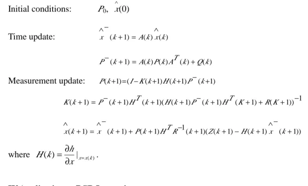
Initial conditions: P0, (0) ∧ x Time update: x (k 1) A(k)x(k) ∧ = + − ∧ ) ( ) ( ) ( ) ( ) 1 (k Ak P k AT k Q k P− + = + Measurement update: P(k+1)=(I−K(k+1)H(k+1)P−(k+1) 1 )) 1 ( ) 1 ( ) 1 ( ) 1 ( )( 1 ( ) 1 ( ) 1 (k+ =P− k+ HT k+ H k+ P− k+ HT K+ +R K+ − K )) 1 ( ) 1 ( ) 1 ( )( 1 ( 1 ) 1 ( ) 1 ( ) 1 ( + − ∧ + − + + − + + + − ∧ = + ∧ k x k H k Z k R T H k P k x k x where ( ) |x x(k) x h k H = ∂ ∂ = . IV.Application to PCB Inspection
A potential application using the proposed scenario is the automated PCB inspection. As a PCB is conveyed and arrived at a inspection site, the two fidicials, usually located at two opposite corners of PCB board, are being imaging; next, the camera is displaced to three different locations making the corresponding imaged points not colinear; and finally the orientation of the PCB is thereafter identified with respect to a reference/world coordinate.
Figure 1.The schematic of a generic PCB inspection site. V.The Simulation and Exper imental Issues
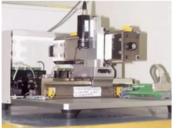
The experimental setup consists of a generic XY-table from UteckZone, a PCI-8134 stepping motor control card from Adlink, and a Domino frame grabber from EuroSys including eVision image analysis tool(Figure 2). The XY-table is programmed to snap a total of 12 flat circular object (calibration point) images with all distinct locations in image plane. Instead of having 12 circular objects on the platform of XY-table, we urge the XY-table to stay at 12 different locations, but those associated image points should be all in
the field-of-view of the camera. All the centers of the circular image objects are computed, and the results are fed into the extended Kalman filter (EKF) to estimate the parameters of transformation matrix. On the other hand, all 12 pairs of world-image points are substituted into a least-squares calculation. In addition to these calibration points, four extra pairs of world-image points are also recorded, and the intersection of the two diagonal lines drawn from these four image points is served as the accuracy verification point. The value of Rk is
a constant, and is computed based on an imaging preprocessing, continuously taking pictures of a stationary point in the world coordinate; the variance of the image coordinates of this stationary point is substituted for Rk.
Figure 2. The XY-Table/vision system.
VI.Summar y
A plausible XY-table in association with a vision system is constructed, and a generic calibration technique is developed to fulfill the XY-table/camera calibration task. An innovative calibration scheme is introduced to overcome the complexity of calibration processes and the use of very costly customized calibration board in most industrial applications.
Basically, a batch processing using least-squares manners achieves the simplicity in computation, but suffers from the non-convergence to the true value. On the contrary, Kalman filter takes the advantages of the noise statistics occurring in imaging system. If the measurement noise (R matrix) can be deliberately estimated before any processing of the
Kalman filter, the estimation accuracy can be further improved. The future work includes the extension of the preceding static calibration issue to the kinematic one. Furthermore, an adaptive Kalman filtering scheme, using time-varying covariance matrices Qk,Rk, may be
used instead of utilizing the current version of Kalman filter with constant Qk,Rk.
Acknowledgements
This research work was fully supported by the National Science Council of ROC under the Contract NSC-90-2516-S-151-008.
Reference
[Ballard and Brown 1982]
Ballard,D.H. and C.M.Brown, Computer Vision, Prentice-Hall, 1982.
[Liang et.al 1989]
Liang,P., Y.L.Chang, and S.H.Hackwood, ”Adaptive Self-Calibration of Vision-Based Robot Systems,”IEEE Trans. on System,Man,and Cybernetics,
vol.19,no.4,1989,pp.811-824. [Renders et al. 1991]
Renders,J-M,E.Rossignol,M.Bacquet,and R.Hanus,”Kinematic Calibration and Geometrical Parameter Identification for Robots,”IEEE Trans. on Robotics and Automation,vol.7,no.6,pp.721-732,1991
[Tang et al. 2000]
Tang,K.K.,S.N.Huang,and J.L.Seet,”Geometrical Error Compensation of Precision Motion Systems Using Radial Basis Function,”IEEE Trans. on Instrumentation and
Mesaurement,vol.49,no.5,pp.984-991,2000.
[Wang 1993]
Kuanchih Wang, Synthesis of Vision-Based Robot Calibration Using Moving Cameras,Ph.D. thesis, Florida Atlantic University, Boca Raton, FL 1993.