444 IEEE TRANSACTIONS ON POWER DELIVERY, VOL. 22, NO. 1, JANUARY 2007
Novel Circuit Topology for
Three-Phase Active Power Filter
Jinn-Chang Wu, Hurng-Liahng Jou, Ya-Tsung Feng, Wen-Pin Hsu, Min-Sheng Huang, and Wen-Jet Hou
Abstract—In this paper, a novel circuit topology for the three-phase active power filter (APF) is proposed to suppress harmonic currents. This three-phase APF is made up of a two-arm bridge power converter, a filter inductor set, a reactive power compensating capacitor set and a capacitor/resistor filtering set. One phase of the three-phase three-wire APF, without control of the power electronic devices, connects directly with any one of the dc terminals. Consequently, the number of power electronic devices employed in the proposed three-phase APF can be re-duced. To demonstrate the performance of the proposed APF, a prototype is developed and tested. Experimental results show that the proposed APF has the expected performance.
Index Terms—Active power filter (APF), harmonic distortion.
I. INTRODUCTION
P
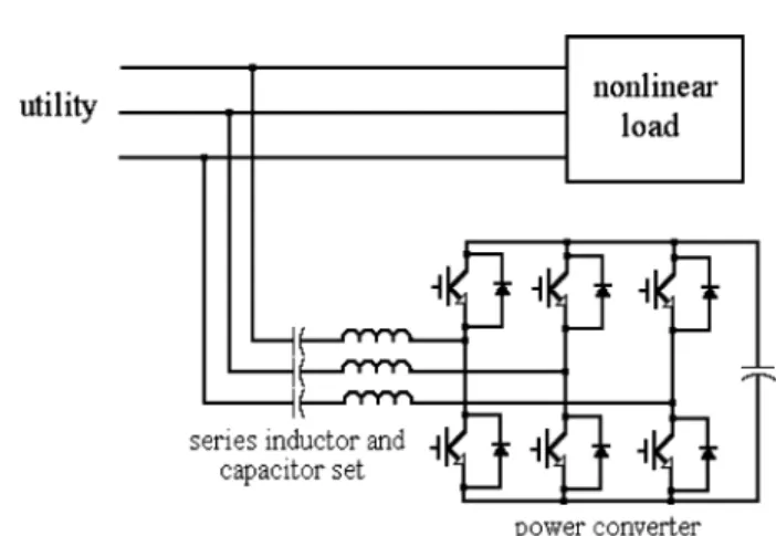
OWER-ELECTRONIC devices with high-voltage rate, high-current rate, and high switching speed characteristics have been developed due to the improvement of semiconductor manufacturing techniques in recent years. Power-electronic devices are applied in electric power equipment, such as the switching power supply, uninterruptible power supply, motor driver, arc furnace, trolley car, battery charger, and lighting appliances. Electric power equipment may generate a large amount of harmonic currents due to the nonlinear input charac-teristic of such loads. The harmonic currents would pollute the power system [1].The active power filter (APF), made up of a power con-verter and passive devices, has been developed to suppress the harmonic current and improve the power factor [2]–[5]. Fig. 1 shows the power circuit of the conventional APF. The passive device connecting the ac terminal of the power con-verter in an APF and the utility is an inductor set that acts as a switching ripple filter. Generally, this APF adopts a current-mode controller to generate three-phase compensation currents. The generated compensation current of each phase in the three-phase APF is the summation of the harmonic compo-nents and fundamental reactive component of load currents. Consequently, the compensation currents are injected into the power lines, and the utility currents are sinusoidal and in phase with the utility voltages. The power converter is a three-arm
Manuscript received June 8, 2005; revised March 13, 2006. Paper no. TPWRD-00345-2005.
J.-C. Wu is with the Department of Electrical Engineering, Kun Shan Univer-sity, Tainan 710, Taiwan, R.O.C. (e-mail: [email protected]).
H.-L. Jou is with the Department of Electrical Engineering, National Kaoh-siung University of Applied Sciences, KaohKaoh-siung 807, Taiwan, R.O.C. (e-mail: [email protected]).
Y.-T. Feng, W.-P. Hsu, M.-S. Huang, and W.-J. Hou are with the UIS Abler Corporation Ltd., Kaohsiung 807, Taiwan, R.O.C.
Digital Object Identifier 10.1109/TPWRD.2006.881416
Fig. 1. Configuration of conventional APF.
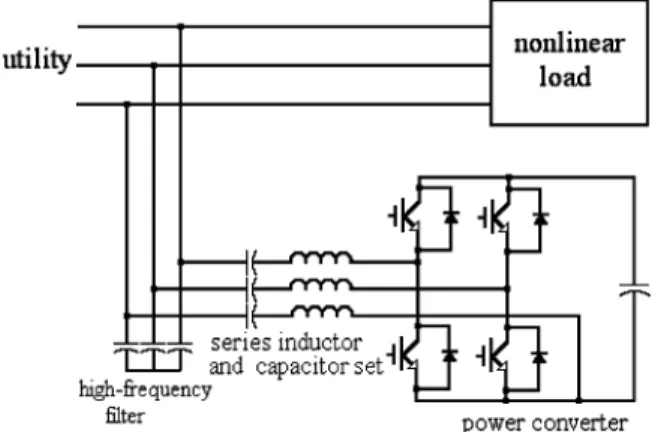
Fig. 2. Configuration of the hybrid power filter.
bridge structure. Although the conventional APF performs better filtering, the capacity of the power converter of the APF must be larger than the product of the harmonic components and fundamental component of the load current and the utility voltage. The capacity and production cost of the power con-verter become very high, thus limiting the applications of the APF.
A series inductor and capacitor set shown as Fig. 2 replaces the passive devices of the APF, and this new filter is named the hybrid power filter [6]–[11]. The series inductor and capacitor set acts as a passive power filter. The hybrid power filter over-comes the high-capacity and high-cost problems caused by the power converter of the APF because the passive power filter can lower the capacity of the power converter. The power converter used in hybrid power filters is also a three-arm bridge structure.
In this paper, a novel circuit topology for an APF is proposed. The passive devices are also a series inductor and capacitor set for reducing the power capacity of the power converter in the
WU et al.: NOVEL CIRCUIT TOPOLOGY FOR THREE-PHASE ACTIVE POWER FILTER 445
Fig. 3. Configuration of proposed APF.
APF. However, the function of the series inductor and capacitor set in the proposed APF is not the same as that of the hybrid power filter. The inductor of the series inductor and capacitor set is used to filter the switching ripple due to switching opera-tion of the power-electronic devices used in the power converter, and the capacitor of the series inductor and capacitor set sup-plies fixed compensation reactive power. The salient advantage of the proposed APF is that the power converter only employs a two-arm bridge structure. In this configuration, one phase of the three-phase three-wire APF, without control of the power-electronic devices, directly connects with any one of the dc ter-minals other than connecting via the series inductor and capac-itor set. Consequently, the number of power-electronic devices employed in the proposed three-phase APF can be reduced. To demonstrate the performance of the proposed APF, a prototype is developed and tested.
II. SYSTEMCONFIGURATION
The system configuration of the proposed three-phase ac-tive power is shown in Fig. 3. The passive devices consist of a high-frequency filter and a series inductor and capacitor set, and the power converter is a two-arm bridge structure. A dc capac-itor is connected to the dc bus of the power converter and creates a dc voltage; therefore, forming a voltage-source power con-verter. The inductor and high-frequency filter are used to filter out the switching ripple generated by the power converter, and the capacitor provides fundamental reactive power and with-stands the major fundamental component of the utility voltage that may reduce the capacity of the power converter.
The voltage-source power converter is controlled by the pulsewidth-modulation (PWM) strategy in which a modulation signal is compared with a high-frequency carrier. In the ideal PWM operation, the output voltage of a single-phase bridge converter with split capacitors can be represented as [12] (1) where and are the switching ripple voltage and gain of the power converter, respectively. Because one power line of the utility is directly connected to the negative terminal of power converter dc bus, the half of dc bus voltage is shifted in the output voltage of the power converter. Then, the output
Fig. 4. Equivalent circuit of the proposed APF system. (a) Under the dc con-dition. (b) Under the fundamental frequency. (c) Under the dominant harmonic frequency.
voltage of the power converter in each arm can be represented as
(2) where is the dc bus voltage of the power converter. The gain
of the power converter can be represented as
(3) where is the amplitude of the high-frequency carrier.
As seen in (2), the output voltage of each arm consists of three parts: a dc component, a amplified modulation com-ponent, and a switching ripple component. Every phase of the proposed APF power contains a capacitor, which can block the dc component of the power converter’s output voltage . Hence, the number of power-electronic devices employed in the three-phase APF can be reduced because one power line of the utility can be directly connected to the negative terminal of the power converter dc bus through no power-electronic devices.
III. SYSTEMANALYSIS
Since the voltage-source power converter controlled by the PWM strategy can generate a voltage as shown in (1), the frequency of switching ripple voltages approximates the product of the integer multiple and the carrier frequency. Since the switching frequency of the power converter is very high compared with the harmonic frequency analyzed in power system, it can be filtered out effectively by the inductor and high-frequency filter. Hence, the switching frequency of the power converter can be neglected in the following discussion. To analyze the performance of the proposed APF under dif-ferent frequencies, the APF system can be divided into three equivalent circuits shown in Fig. 4.
Fig. 4(a) is the equivalent circuit of the proposed APF under the dc condition. Since the utility voltages do not contain any dc component, the utility voltages are regarded as a short cir-cuit. The power converter contains two dc voltage sources in
WU et al.: NOVEL CIRCUIT TOPOLOGY FOR THREE-PHASE ACTIVE POWER FILTER 449
Fig. 13. Experimental result under the unbalanced load condition. (a) Three-phase utility currents. (b) Three-Three-phase load currents.
current is unbalanced seriously. After compensation by the pro-posed APF, the three-phase utility currents are nearly sinusoidal. Compared with Fig. 6, it can found that the experimental result is corresponds with the simulation result.
V. CONCLUSION
A novel circuit configuration of the APF is proposed in this paper. The salient point of the proposed circuit configuration is that the power converter uses a two-arm bridge structure, and the number of power-electronic devices employed in the proposed three-phase APF can be reduced. The proposed APF performs the functions of suppressing harmonic current and supplying fixed reactive power. The computer simulation and experimental results verify that the proposed APF has the expected performance.
REFERENCES
[1] R. D. Henderson and P. J. Rose, “Harmonics: The effects on power quality and transformers,” IEEE Trans. Ind. Appl., vol. 30, no. 3, pp. 528–532, May/Jun. 1994.
[2] A. Abellan, J. M. Benavent, and G. Garcera, “A new control method for obtaining reference currents of shunt active power filters in unbalanced and non-sinusoidal conditions,” in Proc. IEEE ISIE, 1999, pp. 831–836. [3] S. Bala, N. Patel, and B. G. Femandes, “Reduced-switch three-phase active power filter with one cycle control,” in Proc. IEEE Power Eng.
Soc. Conf., 2004, vol. 3, pp. 2333–2339.
[4] J. C. Wu and S. J. Huang, “Design and operations of cascaded ac-tive power filters for the reduction of harmonic distortion in a power system,” Proc. Inst. Elect. Eng., vol. 146, no. 2, pp. 193–199, 1999. [5] T. Jin, J. Wen, and K. Smedley, “Control and topologies for three-phase
three-level active power filters,” in Proc. IEEE IPEMC, 2004, vol. 2, pp. 450–455.
[6] S. Bhattacharya, P. T. Cheng, and D. M. Divan, “Hybrid solutions for improving passive filter performance in high power applications,” IEEE
Trans. Ind. Appl., vol. 33, no. 3, pp. 732–747, May/Jun. 1997.
[7] H. Fujita and H. Akagi, “A practical approach to harmonic compensa-tion in power system, series conneccompensa-tion of passive and active filters,”
IEEE Trans. Ind. Appl., vol. 27, no. 6, pp. 1020–1025, Nov./Dec. 1991.
[8] J. Dixon, J. Espinoza, L. Moran, and D. Rivas, “A simple control scheme for hybrid active power filter,” in Proc. IEEE Power Eng. Soc.
Conf., 2000, pp. 991–996.
[9] H. L. Jou, J. C. Wu, and K. D. Wu, “Parallel operation of passive power filter and hybrid power filter for harmonic suppression,” Proc. Inst.
Elect. Eng., vol. 148, no. 1, pp. 8–14, 2001.
[10] J. Yang, Y. Wang, and Z. Wang, “A DSP controlled hybrid power filter used to compensate the harmonics and reactive power caused by elec-trical traction loads,” in Proc. IEEE Power Eng. Soc. Conf., 2003, pp. 1615–1620.
[11] S. Rahmani, K. A. Al-Haddad, and F. Fnaiech, “A new control tech-nique based on the instantaneous active current applied to shunt hy-brid power filters,” in Proc. IEEE Power Eng. Soc. Conf., 2003, pp. 808–813.
[12] Mohan, Undeland, and Robbins, “Power electronics converters, appli-cations and design,” in Media Enhanced, 3rd ed. New York: Wiley, 2003.
Jinn-Chang Wu was born in Tainan, Taiwan, R.O.C., in 1968. He received the
M.S. and Ph.D. degrees in electrical engineering from National Cheng Kung University, Tainan, in 1992 and 2000, respectively.
Currently, he is an Associate Professor with the Department of Electrical Engineering, Kun Shan University, Tainan. His research interests are in power quality and power-electronic applications.
Hurng-Liahng Jou was born in Taiwan, R.O.C., in 1959. He received the
B.S.E.E. degree from Chung Yuan University, Jonglih, Taiwan, in 1982, and the M.S.E.E and Ph.D.E.E. degrees from National Cheng Kung University, Tainan, in 1984 and 1991, respectively.
Currently, he is a Professor in the Department of Electrical Engineering, Na-tional Kaohsiung University of Applied Sciences, Kaohsiung. His major inter-ests are power-electronics applications and power-quality improvement tech-niques.
Ya-Tsung Feng was born in Taichung, Taiwan, R.O.C., on January 6, 1972.
He received the B.S. degree in electrical engineering from National Kaoshiung University of Applied Sciences, Kaohsiung, in 1999 and the M.S. degree in electrical from National Chiao Tung University, Hsinchu, Taiwan, R.O.C., in 2001.
He was with the R&D Division, UIS Abler Electronics Co., Kaohsiung, for four years. His research interests in power electronics include uninterruptible power supplies (UPS), APFs, and digital controllers.
Wen-Pin Hsu was born in Kaohsiung, Taiwan, R.O.C., in 1974. He received
the M.S degree in electrical engineering from National Cheng Kung University, Tainan, in 2001.
He was with the R&D Division, UIS Abler Electronics Co., Kaohsiung. His research interests include power quality, power electronics, and digital controllers.
Min-Sheng Huang was born in Kaohsiung, Taiwan, R.O.C., in 1980. He
re-ceived the M.S. degree from National Kaohsiung University of Applied Sci-ences, Kaohsiung, in 2004.
He was with the R&D Division, UIS Abler Electronics Co., Kaohsiung. His research interests are power quality, power electronics, and digital controllers.
Wen-Jet Hou was born in Kaohsiung, Taiwan, R.O.C., in 1980. He received
the M.S. degree in electrical engineering from National Cheng Kung University, Tainan, Taiwan, in 2004.
He was with the R&D Division, UIS Abler Electronics Co., Kaohsiung. His research interests are power quality, power electronics, and digital controllers.