108
48
Vol. 17 No. 2 April 2005
MINIATURE ULTRA-LOW-POWER BIOPOTENTIAL
AMPLIFIER FOR POTABLE APPLICATIONS
C
HIA-N
ANC
HIEN, F
U-S
HANJ
AWInstitute of Biomedical Engineering, College of Engineering and College of Medicine,
National Taiwan University, Taipei, Taiwan
Received: Apr 10, 2005; Accepted: Apr 19, 2005 Correspondence: Fu-Shan Jaw, Ph. D.
Institute of Biomedical Engineering, National Taiwan University,
Taipei, Taiwan
E-mail: jaw@ha.mc.ntu.edu.tw
ABSTRACT
A high input impedance, high common mode rejection ratio, fixed gain ( 100) amplifier is proposed for recording biopotential signals. This miniature amplifier affords the feature of power saving. It can continuously function for as long as 3 months with a small battery (3.3 V, 2.2 g). A practical application of this amplifier for ECG recording has shown that it has great potential for recording other biomedical signals. Hence, this amplifier can be used as a building block at the front end of most biomedical systems. Detailed design considerations and circuit implementation of this amplifier are described to facilitate its acceptance as a common module for this purpose.
Biomed Eng Appl Basis Comm, 2005(April); 17: 44-49.
Keywords: amplifier; instrumentation amplifier; low power; portable
1. INTRODUCTION
Amplifiers are usually used at the front end of a recording system to handle the weak signals detected by sensors [1]. Since the biomedical signals are prone to noise interference, it is a common practice to put stringent requirements on the specifications of a biopotential amplifier. The prerequisites for a biopotential amplifier are high input impedance, high gain (calibrated), high common mode rejection ration (CMRR), and electrical isolation [2]. Although many amplifiers have been designed for different biomedical applications [3-6], there is still a need for miniature yet ultra-low-power designs. To this end, we propose a general-purpose biopotential amplifier that is compact in size and could fulfill the requirements of most biomedical signals. A three-operational-amplifier
(3-OP) instrumentation amplifier (IA) was designed with fixed gain to provide the characteristics of high input impedance and high CMRR. Owing to its low-power nature, this amplifier is battery powered for electrical isolation and could be used as the building block of any portable system. A preliminary application of this amplifier to record a rat s electrocardiograph (ECG) is demonstrated. This is achieved by cascading this biopotential amplifier with a 100-Hz low-pass filter to obtain a high-quality recording. Detailed circuit layout of this amplifier is also illustrated.
2. CIRCUIT DESIGN
To provide the characteristics of high input impedance and high CMRR, an IA is usually used as the first stage of a biopotential amplifier. The architectures of an IA can be either the 3-OP type [2] or the current-feedback type [3]. The former features with ease of construction while the latter has inherent higher CMRR. Both types have many commercial products in the single-chip integrated-circuit (IC) form and are ready for use after purchased. However, their power consumption is often too much for portable
109 BIOMEDICAL
ENGINEERING-APPLICATIONS, BASIS & COMMUNICATIONS
49 applications. For simplicity, a 3-OP IA was implemented along with a high efficiency regulated power supply to meet the portable requirement.
The complete circuit diagram of the IA is shown in Fig.1A. A total of 3 OPs were used in this design. To achieve the goal of very low power consumption a quad OP, OP481, consisting of 4 OPs were used. The static current of each OP is only 4 A. As we known that the CMRR of a 3-OP IA depends on the impedance match of the R3 and R4 resistors (see Fig. 1A). To achieve the goal of high CMRR, the gain of the first two OPs was allocated as high as possible while that of the third OP (the differential stage) was kept to unity [4,7]. A lightweight commercial hybrid-lithium battery (AHB401430, 100 mAh, 3.75 V, 2.2 g, SYNergy ScienTech Corp.) was used as the power supply. To avoid the performance degradation of the IA, a low-noise low-dropout linear regulator (G914D) was used to stabilize the supply voltage. As shown in Fig. 1B, the power-supply circuit consists of the G914D and an OP, the 4thOP of the OP481. This OP
was used to split the 3.3 V output of the G914D into 1.65 V and provides a low-impedance system ground.
3. RESULTS
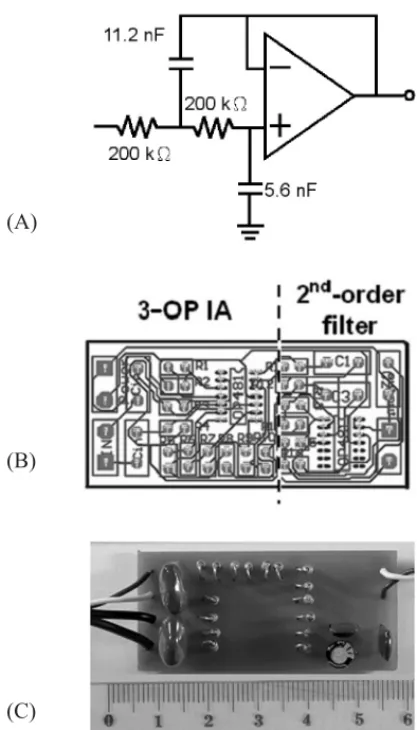
The specifications of the designed biopotential amplifier were measured and listed in the following: gain = 40 dB; maximal input range = 16 mV; background noises = 2.9 V/ Hz (RTI); steady current = 47 A. The frequency response is plotted in Fig. 1C. The passband is from 0.09 to 800 Hz. To further examine the performance of this biopotential amplifier, a 2nd-order Butterworth low-pass filter (as
shown in Fig. 2A) with a corner frequency of 100 Hz was cascaded. This is to form an ECG amplifier for the rat. To facilitate the duplication of the circuit, the layout of the printed circuit is illustrated in Fig. 2B. The dimension of this ECG amplifier is about 5 cm 2.5 cm as shown in Fig. 2C. An example of the measurement is illustrated in Fig. 3. The ECG signal, hardcopy from the screen of the oscilloscope (Tektronix 530A), shows waveform features in great detail; that is, the P wave, QRS complex, as well as T wave could be easily identified.
4. DISCUSSION
A simple yet low-power biopotential amplifier is designed. This amplifier can be used as the building block or module for conditioning biomedical signals. The electrical characteristics of this module were fully measured to confirm that they could meet the
requirements of biomedical applications. To enhance the mechanical strength and reliability during production, this module was implemented on a printed circuit board. An application of this module for ECG recording is illustrated by connecting a low-pass filter next to the output of the amplifier. This suggests that this amplifier can accommodate for various biopotential signals if a suitable filter is cascaded.
An important consideration for portable device is its power consumption must be low enough. As a rough estimation, that the battery capacity can supply stable current to the biopotential amplifier for more
Fig. 1. The biopotential amplifier. (A) Circuit diagram of the 3-OP IA. (B) Circuit of the power supply. (C) Frequency response of the biopotential amplifier. The measured pass-band is from 0.09 to 800 Hz (-3 dB).
(A)
(B)
110
50
Vol. 17 No. 2 April 2005
than 2000 h; i.e. about 3 months without the need to change the battery. Furthermore, the usability of this biopotential amplifier can be demonstrated by the recorded ECG, which possesses high signal-to-noise ratio. Finally, we hope that all this information could be useful to other biomedical colleagues.
ACKNOWLEDGEMENT
This study was supported by grants 93-EC-17-A-05S1-0017 from the Ministry of Economic Affairs, Taiwan, ROC.
REFERENCES
1. Tietze U and Schenk Ch: Measurement circuits. In Electronic Circuits Design and Application. 1990; 767-778.
2. Neuman MR: Biopotential amplifiers. In Webster JG, editor. Medical instrumentation application and design. John Wiley & Sons: New York, 1998; 233-286.
3. Hamstra GH, Peter A and Grimbergen CA: Low-power, low-noise instrumentation amplifier for physiological signals. Med Biol Eng Comput, 1984; 22: 272-274.
4. Dobrev D: Two-electrode low supply voltage electrocardiogram signal amplifier. Med Biol Eng Comput, 2004; 42: 272-276.
5. Amer MB: A design study of a bioelectric amplifier and improvement of its parameters. J Med Eng Technol, 1999; 23: 15-19.
6. Spinelli EM, Martinez NH and Mayosky MA: A single supply biopotential amplifier. Med Eng Phys, 2001; 23: 235-238.
7. Jefferson CB: Special-purpose OP amps. In Operational amplifiers for technicians. Breton publishers: 1983; 281-285.
Fig. 2. An application of this biopotential amplifier. (A) Circuit diagram of the 2nd-order low-pass filter. (B) The layout of the printed circuit and (C) the photograph of the ECG amplifier. Actual dimension can be estimated by the calibration ruler on the photograph.
(A)
(B)
(C)
Fig. 3. The rat s ECG amplified and filtered by the designed circuits.