A Novel Soft Switching Three-Phase Utility Frequency AC to High Frequency AC Direct Power Converter with
PFC Function for Industrial IH Appliance
Takaaki Takahara, Yuki Kawaguchi, Eiji Hiraki and Toshihiko Tanaka
Yamaguchi University
The Graduate School of Science and Engineering 2-16-1 Tokiwadai, Ube, Yamaguchi, Japan
Kazunori Nishimura Hiroshima Institute of Technology
Department of Technology 2-1-1, Miyake, Saeki-ku, Hiroshima, Japan
Abstract— This paper presents performance characteristics of a novel soft switching three phase utility frequency AC (UFAC) to high frequency AC (HFAC) direct converter with PFC function for industrial induction heating and melting applications The proposed “simple three phase system” consists of single phase UFAC to HFAC direct converter in each phase, three phase low pass filter and IH load. This power converter can regulate the output power under a condition of a constant frequency zero voltage soft switching (ZVS) commutation principle on the basis of unique asymmetrical PWM control scheme. In this paper, the input and output characteristics of proposed direct power converter on the basis of computer aided simulation are illustrated and discussed. Furthermore, Y-connected 3φ working coils for IH load with the balanced coupling coefficient in each phase is designed and evaluated from an experimental point of view.
Keywords-component; UFAC-HFAC direcr power converter, power factor correction, soft switching, HF induction heating, coupling coefficient of IH load, asymmetrical PWM
I. INTRODUCTION
The technology using high frequency induction heating (IH) not only fill the key demands of high reliability, safety and cleanliness, but also has excellent advantages of very high thermal conversion efficiency, rapid heating, local spot heating, high power density, and low running cost. In recent years, high frequency power electronics becomes widely used for IH applications. IH technology has been also utilized for domestic applications such as cooking heater, rice cooker and hot water producer, and for industrial circuits such as metal working and super heated steamer.
Power converters changing utility frequency AC power source to high frequency AC like IH appliances cause harmonic currents to utility AC grid. Harmonic currents make utility AC source current non-sine wave and cause low power factor. Low power factor causes increasing of system values. In addition, harmonic currents cause harmonic pollutions in UFAC grid side equipments. To suppress these problem, the officially admitted regulations are provided about harmonic
currents and harmonic contents[1], as well as effective power factor [2] in UFAC grid side.
Generally, the high frequency IH apparatuses based on the high frequency power conversion equipments have PFC rectifier stage or diode bridge rectifier stage as passive PFC converter (UFAC-DC) and high frequency resonant inverter stage for supplying high frequency AC power to various IH load structures (DC-HFAC). These IH products have high power factor and low utility AC current harmonics characteristics. However, the IH products are actually needed a lot of power semiconductor devices, passive resonant circuit components and bulky electrolytic voltage smoothing capacitor stack.
From these present backgrounds, this paper proposes soft switching three-phase utility frequency AC to high frequency AC direct converter with PFC function for industrial IH appliance, especially for hot water producers or super heated steamer. Proposed “simple three phase system” consists of single phase UFAC to HFAC direct power converter in each phase, three phase low pass LC filter and IH load using Y- connected working coils. This power converter can regulate its output power under a condition of a constant frequency zero voltage soft switching (ZVS) commutation principle on the basis of a unique asymmetrical PWM control scheme. This paper evaluates the input and output characteristics of proposed circuit on the basis of simulation. Furthermore, 3φ Y-connected working coils for IH load with the balanced coupling coefficient in each phase are evaluated from an experiment point of view.
II. PROPOSED CIRCUIT CONFIGULATION AND ITS CONTROL SCHEME
A. Proposed circuit configulation
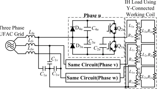
Figure 1 illustrates proposed soft switching three phase UFAC-HFAC direct power converter. This frequency power converter consists of low pass filter Lf, C1 with neutral point, three single phase UFAC-HFAC direct converters in each phase and “three winding input / single winding IH load”. The
single phase direct converter consists of active switching power devices Q1(S1/D1), Q2(S2/D2), diodes D3, D4, resonant capacitors C3, C4 and lossless snubbing capacitor C2. 200Vrms utility frequency AC grid is connected via LC filer with neutral point. Any balky DC smoothing capacitor is not necessary in this proposed direct frequency power converter. Single-phase UFAC-HFAC direct frequency converter in each phase can directly converts 60Hz power of UFAC grid into 24 kHz HFAC power and supplies high frequency AC to load working coil. This converter can operate with asymmetrical PWM (APWM) to regulate output high frequency AC power. Active switches Q1 and Q2 are operated under ZVS&ZCS turn on and ZVS turn off by loss-less snubbing capacitor C2x(x; u, v, w).
The output IH load has three working coils at each phase and a heated object is set up in these working coils. The equivalent IH load circuit which includes the magnetically coupled components of working coil R1x, L1x (x; u, v, w) can be described as shown in Fig.1. Three phase UFAC-HFAC direct power converter is composed of three units single phase ones at each phase intermediated neutral conductor. The circuit parameters and design specifications of proposed three-phase AC-HFAC direct converter are listed in Table I.
B. Operating principle
As shown in Fig. 2, roles of the switches Q1 & Q2 in the bridge leg change under synchronizing with the polarity of the input AC phase voltage. In addition to this, roles of the resonant capacitors C3 & C4 exchange. In case of the input AC phase voltage vx(x; u, v, w) < 0, Q1 works as power regulating main switch and C3 works as resonant and clamp capacitor, on the contrary, switch Q2 works as main switch and C4 works as resonant capacitor at vx(x; u, v, w)<0. The definition of the duty factor is expressed by eq.(1).
T
D=Ton (1)
Ton is gate injection time of the main switch; T is one cycle of switching period. At the changing points of the polarity of the input AC phase voltage, roles of resonant capacitors C3 &C4
C3u C2u
C4u Q2u
Q1u
D4u L1u
L1v
L1w
R2u
R1u
R1w
R1v
L2u
Same Circuit(Phase v) Same Circuit(Phase w) C1u
Lfu
C1w
C1v Lfw
Lfv
D3u
Phase u
R2v
L2v
R2w
L2w
Three Phase UFAC Grid
IH Load Using Y-Connected Working Coil
Fig. 1. Proposed circuit configuration of three-phase AC-AC direct converter.
TABLE I.CIRCUIT PARAMETERS OF PROPOSED POWER CONVERTER
Item Symbol Value
AC Source Voltage Vac 200[V]
AC Source Frequency fin 60[Hz]
Switching Frequency fSW 24[kHz]
Dead Time Td 1.0[µsec]
Inductance of Filter Inductor Lf 1.3[mH]
Capacitance of Filter Capacitor C1 6.6[µF]
Capacitance of Lossless Snubber
Capacitor C2 45.2[nF]
Capacitance of Resonant Capacitor C3 6.6[µF]
Capacitance of Resonant Capacitor C4 6.6[µF]
Phase Voltage vx
Triangular Wave FactorDuty
(D=0.8)
Modulated Signal
Q2
Gate Pulse Q1
Gate Pulse
Ton
T
Ton
T Fig. 2. Principle diagram of APWM control method
exchange each other. At this time, residual electric charge remains at resonant capacitor. After phase voltage zero crossing point, residual charge is discharged by switching.
This discharging currents cause harmonic currents and low power factor in input current. To avoid this problem, the gate signals in each phase are sifted 2π/3 of switching frequency each other. These gate signals can be generated by the sifted triangular waves for the PWM operation. By this modulation method, remained voltage can be reduced and harmonic currents are suppressed [3].
III. OUTPUT AND INPUT CHARACTERISTICS
A. FFT analysis of input currents
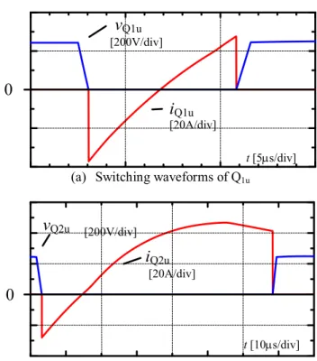
Fig. 3 shows voltage and current waveforms of the switches Q1 & Q2 in case of duty factor D=0.8 at the positive peak point area in phase u. Observing this figure, all the switches can achieve soft switching operation, under ZVS&ZCS turn on and ZVS turn off condition.
Simulated input line voltage and current waveforms are illustrated in Fig. 4. Line current iu seems to be sinusoidal waveform. Line current phase lags about π/2 compared with line voltage vvw. Fig. 5 illustrates FFT analysis of utility AC side line current for phase u. All harmonics are suppressed under regulation [1]. This shows excellent PFC performance of proposed circuit. Observing the simulated results, proposed direct converter can achieve under regulation in duty factor D<0.9.
B. Converter output characteristics
Fig. 6 illustrates three phase UFAC-HFAC direct converter output currents. This figure shows single phase converter operates in envelop curve of utility AC. Therefore, in single phase converter, eddy current in envelop curve of utility AC flows in heated object. However, this envelop curve has possibilities of delay heating responses. But, in three phase direct converter, triple eddy currents flow through heated object. The pulsation of eddy current in heated object can be reduced as compared with single phase converter. Proposed three phase UFAC-HFAC direct converter can achieve not only
0
vQ1u
[200V/div]
iQ1u
[20A/div]
t [5µs/div]
(a) Switching waveforms of Q1u
0
vQ2u [200V/div]
iQ2u [20A/div]
t [10µs/div]
(b) Switching waveforms of Q2u
Fig. 3. Simulated waveforms of Q1u, Q2u (vu>0, D=0.8).
t[5ms/div]
i
u[10A/div]v
vw[100V/div]
0 π/2
Fig. 4 Waveforms of input voltage and current.
0.0001 0.001 0.01 0.1 1 10
1 10 20 30
Harmonic Current[A]
Harmonic Order n
Simulated result Limited Value [1]
40 100
Fig. 5 FFT analysis of utility AC power source side current (D=0.8).
iuout [30A/div]
ivout
[30A/div] iwout [30A/div]
t[5ms/div]
0
Fig. 6 Simulated output current waveforms.
large capacity IH but also stable heating characteristics as compared with single phase direct converter.
Input power and power factor characteristics are illustrated in Fig. 7. As can be seen, proposed direct power conversion circuit can fill power factor regulation [2] in D≥0.2.
Furthermore, proposed converter can operate under soft switching condition in D≥0.3. In 0.2≤D<0.3, direct UFAC- HFAC converter operates under a hard switching commutation, but it is possible to operate because of low input power. From input and output characteristics, a duty factor D operated range of three phase UFAC-HFAC direct converter is defined as 0.2≤D<0.9.
IV. HIGH FREQUENCY INDUCTION HEATING BOILER FOR
PIPE LINE INDUSTRIAL FLUID HEATING
A. Equivalent circuit of epock making IH boiler
The schematic diagram of single phase IH boiler for fluid heating used in pipe line is shown in Fig. 8. This boiler consists of spiral type dual pack IH element, working coil and non- metal heating vessel. It is composed of the stainless steal spiral assembly and its outside edge point is connected to the inside edge point by the copper bar. In this assemble technique, it is possible to achieve rapid heating response of this induction fluid power heating appliance because of electromagnetic induction eddy current flows through this heat exchanger entirely. Fig. 9(a) represents transformer type equivalent model of IH boiler. This model is represented as the self-inductance L1 and internal resistance R1 of the working coil, self- inductance L2 of eddy current heated element in electromagnetic induction transformer secondary side and mutual inductance M between L1 and L2. M is defined as
2 1
12 LL
k
M = (2)
where k12: electromagnetic coupled coefficient between L1 and L2. The circuit equations in transformer primary side and secondary side are as follows;
v1=jω(L1-M)i1+jωM(i1+i2)+R1i1 (3) 0=jω(L2-M)i1+jωM(i1+i2)+R2i2, (4) where v1: the voltage of primary side, i1 and i2: the currents of primary and secondary side and ω: the operating angular frequency of high frequency AC from direct power frequency converter. The voltage v1 of primary side can be derived from (3) and (4);
0.5 0.6 0.7 0.8 0.9 1
0 2 4 6 8
0.1 0.3 0.5 0.7 0.9
Output Power Power Factor Soft Switching Area
0.85
0.2
Power Factor Regulation [2]
Regulation Matching Area
Input Power P[kW] Input Power Factor
Duty Factor D
Fig. 7 Input power and power factor vs. duty factor.
(a) Involuted type heat exchanger
(b) Prototype of induction heating boiler
Working coil Super heated
steam
HFAC Power Source
Input water Non-metal
heating vessel Copper Bar of end ring
for the short circuit Spiral type heating element
(c) Schematic diagram of induction heating boiler Fig. 8. Internal structure of induction heating boiler and
its exterior appearance.
L1 R2
R1
L2
M
i1 i2
v1
L0
R0
i1
v1
(a)Transformer model (b)Simplifyed model
Fig. 9. Equivalent circuit of single IH load.
1.
2 2 2 2 2 2
2 2 1 2
2 2 2 2 2
2 2 1
1 L i
L R L M j L R
R R M
v
⋅
− +
+
⋅
+ +
= ω
ω ω ω
ω
However, the result impedance of transformer type equivalent (5) IH model is defined as
Z=(R1+AR2)+jω(L1-AL2)
=R0+jωL0, (6)
where L0: effective equivalent inductance, R0: effective equivalent resistance. A is;
2.
2 2 2 2
2 2
R L A M
= + ω
ω (7)
From eq.(5), the equivalent circuit model of IH load is illustrated as simple equivalent inductive circuit model in Fig.
9(b). The measurable parameter measured from working coil ports are used for simulation because it is impossible to measure self-inductance L2 and skin-effect related resistance R2
in secondary side.
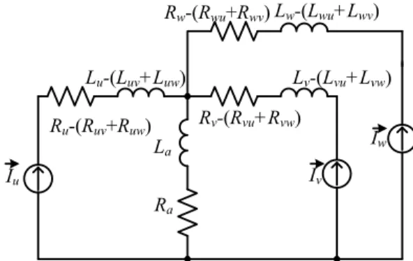
B. IH boiler with three phase high frequency working coil Three phase UFAC-HFAC direct converter has one unit IH load in each phase direct converter in Fig. 1. IH boiler with three phase working coil has triple separate working coils with one heated object. Mutual induction occurs between working coils in each phase. Fig. 10 shows equivalent circuit of three phase connected IH load in coupled with each phase working coil. In this figure, the unit direct converters in each phase are simulated as current sources. Each circuit parameter in Fig. 11 is derived with equivalent effective inductance Lx(x; u, v, w), equivalent effective resistance Rx(x; u, v, w) and coupled coefficient k among each working coil. Inductance La and resistance Ra by mutual induction are defined;
Ra=Ruv+Ruw=Rvu+Rvw=Rwu+Rwv (8) La=Luv+Luw=Lvu+Lvw=Lwu+Lwv, (9) where Rxy and Lxy (x, y; u, v, w ,x≠y): resistance and inductance components by mutual induction between phase x and phase y.
Mutual inductance Luv and Luw is represented by;
u.
v u uw
uv L k L L kL
L = = = (10)
Mutual inductance in phase u can be defined as
La=Luv+Luw=2kLu (11)
Lu-(Luv+Luw)=(1-2k)Lu. (12) On the other hand, resistance by mutual induction and in phase u can be defined as
Ra=Ruv+Ruw=2kRu (13)
Ru-(Ruv+Ruw)=(1-2k)Ru. (14) Eqs.(11)-(14) shows that mutual inductions of two working coils are induced to one working coil in three phase working coil type IH boiler.
V. PROTOTYPE OF THREE PHASE
WORKING COIL TYPE IHBOILER
Working coils for IH load with the balanced coupling coefficient in each phase is discussed from an experiment point of view. This working coils is practically designed for the following specific conditions:
(a) phase coupled coefficient k≤0.25
(b) phase coupled coefficient is symmetric between each phase.
In the first condition (a), it is necessary for three phase type working coils have weak coupling. In the second condition (b), the coil currents tend to be unbalance, because mutual inductances are unbalance.
The prototype of working coils is shown in Fig. 11. This model has working coils in phase u and v between half of working coil in phase w and half of one. Self-inductance L in each phase is defined;
l S n
L=Kµ 2 (15)
where K: nagaoka coefficient, µ: space permeability, n: coil turns numbers and S: coil sectional area. Coupled coefficient k is shown by
) (
) (
1 1 2 2
uv u u
uv u
L L L
L k L
−
−
= +ω
ω (16)
La
Ra
Ru-(Ruv+Ruw) Lu-(Luv+Luw)
Rw-(Rwu+Rwv) Lw-(Lwu+Lwv)
Rv-(Rvu+Rvw)
Lv-(Lvu+Lvw)
Iw
Iv
Iu
Fig. 10. Equivalent circuit of three phase IH load.
where Lu: self-inductance in phase u and Luv: inductance in phase u when terminals in phase v are shorted.
Coupling coefficient of working coil model is indicated in Table II. As can be seen, every coupling coefficient are balanced. Accordingly, the working coil model is suitable for three phase working coil type IH boiler.
VI. CONCLUSIONS
This paper evaluated the input and output characteristics of proposed three phase UFAC-HFAC direct power frequency conversion circuit on the basis of computer aided simulation.
A novel soft switching three phase UFAC-HFAC direct converter with PFC function was discussed. Wide soft switching operation area and fine output power regulation characteristics are ascertained computer aided simulation. The input current harmonics and power factor in UFAC grid side were suppressed under limited value by asymmetrical PWM control. From the characteristics of proposed three phase UFAC-HFAC direct power converter, the duty factor D as a control variable was determined in 0.2≤D<0.9.
Furthermore, new working coils design for IH load with the balanced coupling coefficient in each phase was evaluated from a theoretical point of view. The working coils are practically designed for the following specific conditions:
(a) phase coupled coefficient k≤0.25
(b) phase coupled coefficient is symmetric between each phase.
In practical case, it has seemed every coupling coefficient of new working coil assembly was balanced. This working coil model is suitable for three phase working coil type IH boiler.
REFERENCES
[1] Electromagnetic compatibility “IEC 61000-3-2” , 2005.
[2] The Chugoku Electric Power CO.,INC, “Electricity Supply Contracts” , September 1, 2008.pp.127-132
[3] Takaaki Takahara, Eiji Hiraki, Toshihiko Tanaka, “Characteristics of a three-phase AC-AC Direct Converter with PFC Function for High Frequency IH”, 2009 Annual Conference of IEE Japan, Sapporo, pp.113-114
[4] Masahiro Nakao, Eiji Hiraki, Toshihiko Tanaka, Mutsuo Nakaoka,
“Characteristic Evaluations of Three-Phase AC-AC Direct Converter with PFC Function”, IEICE Technical Report, 2006, February, Japan [5] Hisayuki Sugimura, Sang-Pil Mun, Soon-Kurl Kwon, Tomokazu
Mishima, Mutsuo Nakaoka, “High-Frequency Resonant Matrix One- Chip Reverse Blocking IGBT-Based Bidirectional Switchies fof Induction Heating”, Power Electronics Specialists Conference, June, 2008, pp.3960-3966
[6] H. N. Pham, H. Fujita, N. Uchida, K. Ozaki, “Analysis of Heat Distribution in a Zone-Control Induction Heating System”, 2008 Annual Conference of IEE Japan, Fukuoka, pp.89-90
[7] Hideaki Fujita, Naoki Uchida, Kazuhiro Ozaki, “Zone Controlled Induction Heating (ZCIH) –A New Concept in Induction heating-”,2007 Power Conversion Conference, Nagoya, pp.1498-1504
TABLE II. COUPLING COEFFICIENT OF WORKING COIL MODEL
Phase u-v Phase v-w Phase w-u kuv 0.21 kvw 0.25 kwu 0.22 kvu 0.22 kwv 0.24 kuw 0.21
Phase u Phase w
Phase v
(a) Schematic diagram
(b) Prototype three phase Y-connected working coils Fig. 11. Trial produced working coil model.