I-Shou University Institutional Repository:Item 987654321/11546
52
0
0
全文
(2) Inconel 718 超合金高溫潛變性質 High Temperature Creep Behavior of Inconel 718 Superalloy. 研 究 生 : 阮明律. Student : Minh Luat Nguyen. 指 導 教 授 : 郭振明博士 Advisor : Dr. Chen-Ming Kuo 義 守 大 學 機械與自動化工程學系 碩士論文. A Thesis Submitted to Department of Mechanical and Automation Engineering I-Shou University In Partial Fulfillment of the Requirements For the Master degree in Mechanical and Automation Engineering December, 2009 Kaohsiung, Taiwan, Republic of China. 中 華 民 國 九 十 九 年 一月.
(3)
(4) ABSTRACT Standard heat treatment for Inconel 718 superalloy is solutionizing at 1095°C, 1 h/AC, then aging at 955°C, 1 h/AC + 720°C, 8 h/FC 57K/h to 620°C, 8 h/AC. In order to study some effects of process and microstructure on high temperature creep behavior, creep tests were conducted in this research. Lever arm creep tests were performed at 650°C under constant stress of 625 MPa. In this experiment, the performance of Inconel 718 using recast process were compared with another kind of Inconel 718 using forged process, to investigate high temperature creep behavior of Inconel 718 superalloy performed at the same heat treatment process. The creep rupture life time of forged Inconel 718 is (about 1800 hours) much longer than that of recast Inconel 718 (about 120 hours). The very different results showed that the process and microstructure have significantly influences on the mechanical properties of Inconel 718 superalloy. By the use of OM and SEM, porosities are found in the recast 718 specimens. The percentage of porosity is so high that has main harmful effect on creep behavior. Hardness and grain size were measured after heat treatment scheme.. Keywords: Inconel 718, Creep Behavior, Heat Treatment, High Temperature Creep Test, Microstructure. I.
(5) ACKNOWLEDGEMENT In writing this thesis, I have owed much intellectual debt. While I cannot possibly thank every single individual, a number of people deserve special mention for their contributions. I am indebted particularly to my supervisor, Dr. Chen-Ming Kuo for his thoughtfulness, patience and tireless academic support. The guidance he gave me throughout the process in preparing this thesis, from searching for references, advice and comments on my progress and has been crucial in bringing this research to fruition. I would also like to thank Dr. An-Chou Yeh for his great source of information on superalloy technology, Mr. Y.-C. Tai for giving me many beautiful OM/SEM pictures in my thesis, Mr. Kang-Wei Lu for preparing specimens and conducting experiments for me. I would like to acknowledge my best friends Huu-Tri Nguyen, Chun-Yu Lin, Ping Li, ChienChih Chen for source of information, some of my data and figures were supply by them. Finally, I would like to give my special thanks to my family for their patience and love that enabled me to complete this work.. II.
(6) TABLE OF CONTENTS ABSTRACT .....................................................................................................I ACKNOWLEDGEMENT ............................................................................. II TABLE OF CONTENTS .............................................................................. III LIST OF FIGURES........................................................................................ V LIST OF TABLES ...................................................................................... VII CHAPTER I INTRODUCTION ..................................................................... 1 CHAPTER II THEORETICAL BACKGROUND ......................................... 5 2.1 Influence of Alloy Elements ............................................................. 5 2.2 Precipitation Phases and Structural Characteristics.......................... 7 2.2.1 γ-phase ...................................................................................................... 7 2.2.2 γ′ phase...................................................................................................... 7 2.2.3 γ" phase..................................................................................................... 7 2.2.4 δ-phase ...................................................................................................... 7 2.2.5 Carbides .................................................................................................... 8 . 2.3 Effect of Heat Treatment on the Precipitate Phases.......................... 8 2.4 Principles of Electron Energy Dispersive X-ray Spectroscopy ........ 8 2.5 Creep Definition................................................................................ 9 CHAPTER III EXPERIMENTAL PROCEDURES..................................... 14 3.1 Experimental Materials ................................................................... 14 3.2 Heat Treatment Process................................................................... 14 3.3 Rockwell Hardness Testing ............................................................ 14 3.4 Grain Size Measurement ................................................................. 15 3.5 SEM Observation ............................................................................ 15 3.6 High Temperature Creep Test......................................................... 16 CHAPTER IV RESULTS AND DISCUSSTIONS ...................................... 21 4.1 OM Observation.............................................................................. 21 III.
(7) 4.2 SEM observation and EDX............................................................. 21 4.3 Rockwell Hardness Measurement................................................... 21 4.4 Porosity............................................................................................ 22 4.5 High Temperature Creep Behavior ................................................. 22 CHAPTER V CONCLUSIONS.................................................................... 39 REFERENCES.............................................................................................. 40 . IV.
(8) LIST OF FIGURES Figure 1-1: An old photo of the Heinkel He-178 world’s first jet aircraft[1]. . 3 Figure 1-2: Turbine engine structure diagram[3]. ............................................ 3 Figure 1-3: The engine to withstand both temperature and pressure[4]........... 4 Figure 1-4: Comparison of creep curves for Mar-M200 tested at 1255 K and 206.8 MPa in (a) conventionally cast, (b) directionally solidified, and (c) single crystal forms. ............................................................................ 4 Figure 2-1: (a) FCC γ' structure, (b) BCT γ" structure[15]. ............................ 10 Figure 2-2: Volume fraction and aging time relationship between γ" and δ phases[17]. ........................................................................................... 10 Figure 2-3: Solid solution and the effect of temperature diagram[22]............ 11 Figure 2-4: The temperature range for the existence of precipitates of Inconel 718[23]................................................................................................. 11 Figure 2-5: Transportation phases of Inconel 718. ....................................... 12 Figure 2-6: Elemental Energy dispersive X-ray microanalyses of the mineral crust of Rimicaris exoculata.............................................................. 12 Figure 2-7: Creep strain versus time graph. .................................................. 13 Figure 3-1: the TTT diagram of Inconel 718[27]............................................ 18 Figure 3-2: Heat treatment scheme. .............................................................. 18 Figure 3-3: Heat treatment furnace. .............................................................. 19 Figure 3-5: ATS series 2330 lever arm creep tester...................................... 20 Figure 3-6: Creep test specimen specifications............................................. 20 Figure 4-1: Cross sectional view of a recast Inconel 718 specimen after heat treatment............................................................................................ 26 Figure 4-2: Optical Microscope pictures showing porosities of a recast Inconel 718 specimen, (a) 200X, (b) 500X.................................................... 27 Figure 4-3: SEM image showing carbides of as-received recast Inconel 718.28 . V.
(9) Figure 4-4: SEM image showing carbides of as-received forged Inconel 718[28]. ........................................................................................................... 28 Figure 4-5: SEM image with EDX position showing carbides of as-received recast Inconel 718. ............................................................................ 29 Figure 4-6: SEM image with EDX position showing carbides of as-received forged Inconel 718 [28]. ...................................................................... 29 Figure 4-7: SEM images showing porosity of original material recast Inconel 718, (a) 50X, (b)100X....................................................................... 30 Figure 4-8: SEM image showing carbides of recast Inconel 718 after heat treatment............................................................................................ 31 Figure 4-9: SEM image showing carbides of Forged Inconel 718 after heat treatment[28]. ...................................................................................... 31 Figure 4-10: SEM image with EDX position showing carbides of recast Inconel 718 after heat treatment..................................................................... 32 Figure 4-11: SEM image with EDX position showing carbides of forged Inconel 718 after heat treatment [28]................................................................ 32 Figure 4-12: : SEM images showing porosity of recast Inconel 718 after heat treatment, (a) 50X, (b) 250X............................................................ 33 Figure 4-13: Hardness testing locations of a specimen cross section........... 34 Figure 4-14: Creep curves of recast and forged Inconel 718 specimens under constant tensile stress 625 MPa at 650°C. ........................................ 35 Figure 4-16: SEM fractographs of a crept forged Inconel 718 specimen, (a) 100X, (b) 300X. ................................................................................ 37 Figure 4-17: Fracture surface of a crept recast Inconel 718 specimen shows rapid crack propagation. ............................................................................. 38 Figure 4-18: Fracture surface of a crept forged Inconel 718 specimen shows slow crack propagation. .................................................................... 38 . VI.
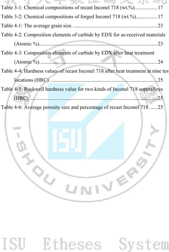
(10) LIST OF TABLES Table 3-1: Chemical compositions of recast Inconel 718 (wt.%)................. 17 Table 3-2: Chemical compositions of forged Inconel 718 (wt.%)................ 17 Table 4-1: The average grain size. ................................................................ 23 Table 4-2: Composition elements of carbide by EDX for as-received materials (Atomic %).......................................................................................... 23 Table 4-3: Composition elements of carbide by EDX after heat treatment (Atomic %).......................................................................................... 24 Table 4-4: Hardness values of recast Inconel 718 after heat treatment at nine test locations (HRC). ................................................................................. 25 Table 4-5: Rockwell hardness value for two kinds of Inconel 718 superalloys (HRC). ................................................................................................. 25 Table 4-6: Average porosity size and percentage of recast Inconel 718. ..... 25 . VII.
(11) CHAPTER I INTRODUCTION For nearly three decades since the middle of World War Two, the insatiable demands of the turbine engines that power our high performance military and commercial aircraft, as well as our industrial turbines, have motivated a search for new materials.. The first world war’s. jet aircraft was the German-made aircraft He-178[1] (Figure 1-1); the inventor was a German aircraft designer Ernst Heinkel[2], along with gas turbine expert Hans Von Ohain. Turbine engines[3] (Figure 1-2) are a primary flight power source for aircraft. The principle is that the air is inhaled through the front of the engine, passes through a compressor stage where it is pressurized, and finally moves to the combustion chamber where it is mixed with fuel ignited. The expansion of the post-high-pressure high-temperature gases emitted from the rear provides thrust that pushes the aircraft forward. In order to enhance the performance of turbine engines more effectively, turbine engines operate at and have to withstand higher temperatures. From Figure 1-3 it can be seen that the relationship between temperature and pressure, in turn the turbine engines prompted the development of Superalloys[4]. Inconel 718, a Nickel-iron-base superalloy[4,5], was developed by International Nickel Corporation in the 1950s and can be found in many applications of turbine components. Although Inconel 718 has been introduced for a long time, it is still widely used in many applications, especially under high-temperature environment such as the turbine engine, cogeneration, and heat treatment equipments. Superalloys have many advantages such as high-temperature strength and toughness[4,6,7]. Aside from that, thermal fatigue, oxidation resistance, corrosion resistance, and easiness to forge, weld, and braze were the advantages of Inconel 718[8,9]. Inconel 718 belongs to the Ni–Fe based superalloy families which cover a wide range of compositions and mechanical properties. Ni and Cr provide resistance to corrosion, oxidation, carburizing, and other damaging mechanism that act at high temperature. Inconel alloys have good cryogenic properties, fatigue, and mechanical strength at moderate temperatures and relatively good creep behavior as shown in Figure 1-4. Usually, Inconel alloys are extraalloyed with Al, Ti, Nb, Co, Cu and W to increase mechanical and corrosion resistance. Fe can also be present in amounts ranging 1–20%. These superalloys are intended for heat treatment recipients, turbines, aviation, and nuclear power plants. Both solid solution and precipitation strengthening are the major steps in strengthening mechanisms[4,5], so that the heat treatment scheme of Inconel 718 is divided into solid solution treatment and aging treatment. The standard solution treatment temperature was at 980°C, and 1.
(12) then double aging at 720°C + 620°C; but later on, the solution temperature was fixed to 1032°C. It was found that Laves phases and carbides could not be solved under 1032°C. However, if the temperature rises to 1095°C, some Laves phases and carbides could be solved back to the matrix. The δ phase was considered a harmful one, but it was recently reported[10] that the δ phase could control the grain size and block grain boundary sliding. In Inconel 718, δ phase formation occurs over the 650–980°C temperature range with platelet morphology[5]. In this study, microstructure after heat treatment schemes was observed and high-temperature creep behavior has been investigated. Correlations between microstructure and creep behavior are discussed.. 2.
(13) Figure 1-1: An old photo of the Heinkel He-178 world’s first jet aircraft[1].. Figure 1-2: Turbine engine structure diagram[3].. 3.
(14) Figure 1-3: The engine to withstand both temperature and pressure[4].. Figure 1-4: Comparison of creep curves for Mar-M200 tested at 1255 K and 206.8 MPa in (a) conventionally cast, (b) directionally solidified, and (c) single crystal forms.. 4.
(15) CHAPTER II THEORETICAL BACKGROUND The mechanical properties are very much dependent on the alloying elements, microstructures, and material processes. Elements of Inconel 718 can produce great effects on material characteristics; therefore, we need to know the effect on the relative mechanical properties of added elements and precipitations.. 2.1 Influence of Alloy Elements (1) Nickel (Ni) Nickel is the main component of Inconel 718. The Nickel content is about 50-55 % and gives the greatest improvement to yield strength. Because it contains a lot of nickel, Inconel 718 has excellent high-temperature oxidation resistance, high temperature tensile, and creep strength. (2) Niobium (Nb) Niobium is the main precipitation hardening element of Inconel 718. Niobium content is at about 4.65-5.4 % to improve ductility and strength. Niobium is integrated with the base for the formation of Nb (coherent), the body-centered cubic structure (BCT) of the γ" phase, and the base of the non-integration (incoherent) fraction of the δ phase and NbC carbide. (3)Tantalum (Ta) As Niobium for the precipitation hardening element, Tantalum will have TaC carbide precipitation. (4)Titanium (Ti) Titanium is one of the elements for precipitation hardening carbides; the content is about 0.65-1.15 %. Easily associated with Nickel to form integrated phase γ' and carbide TiC. (5) Aluminum (Al) Aluminium is one of the elements for precipitation hardening and oxidation resistance; the content is about 0.4-0.8 %, which gives the best yield strength. As Nickel and Titanium would be the formation of γ′ phase to increase its strength. Aluminium content increases, laves phase content will be enhanced. Aluminium can delay over-aging of γ′ phase, to decrease hardness of materials. (6) Boron (B) Boron can improve the creep stress-rupture strength and the extension of time to prevent the grain boundary movement, generally the content is [11]. about 0.006%. . 5.
(16) (7) Silicon (Si) Small amount of silicon gives a slight improvement in strength; the content is about 0.35%. Prompting the formation of laves phase and M6C carbides and reducing the stress rupture time. Reducing the silicon content. can. improve. the. ductility. and. toughness,. and. increase. the. intermetallic compounds NbC and the amount of δ phase. (8) Nitrogen (N) With Ti to form TiN, Nitrogen allows the precipitation strengthening element of Ti to be consumed, thus reducing the formation of Ti γ' phase and the strength of the material. (9) Chromium (Cr) Chromium increases the workability at high-temperature and anti-oxidation properties, as well as solving strengthening austenitic base, in addition to reinforce strength. The content is about 17.0- 21.0%. (10) Molybdenum (Mo) The mechanical properties of Molybdenum greatly depend on the amount of working performed below the recrystallization temperature and on the ductile-to-brittle transition temperature. The Mo content is about 2.8-3.3%. (11) Iron (Fe) Ferrous elements in Inconel 718, after the main components of nickel (Ni), can improve the weld properties. (12) Cobalt (Co) Cobalt affects the amount of precipitates, increasing γ' and γ "precipitates; this helps to increase the strength of the material. (13) Sulphur (S) Sulphur can enhance high-temperature stress properties and can also improve the ductility; the usual content is 0.001% or less[12]. (14) Phosphorus (P) Phosphorus promotes general precipitation for carbides, it increases stress rupture life and ductility. Phosphorus also improves the creep property and crack propagation resistance of Inconel 718. The content is usually below 0.015%[13].. 6.
(17) 2.2 Precipitation Phases and Structural Characteristics 2.2.1 γ-phase For the Inconel 718, γ is the base phase. The continuous matrix is an FCC (Face Centered Cubic). Nickel-base austenitic phase called gamma that usually contains a high percentage of solid solution elements such as cobalt, chromium, molybdenum and tungsten[14]. 2.2.2 γ′ phase Principle strengthening phase in many nickel- and nickel-iron-base superalloys, the crystal lattice varies slightly in size (0 to 0.5%) from that of austenite matrix; the shape varies from spherical to cubic; the size varies with exposure time and temperature; and the strength of γ′ increases as temperature increases. γ' phase is the integral element of Ni3(Al,Ti), for the FCC (L12) structure, as shown in Figure 2-1(a)[15]. The volume fraction, size, and distribution of γ´ are important parameters for the controlling of properties. The volume fraction of γ´ increase with the addition of aluminum and titanium, but the amounts of each must be carefully controlled. 2.2.3 γ" phase Principal strengthening phase in Inconel 718 to form elements Ni3Nb, part of the bodycentered cubic crystal structure (BCT), as shown in Figure 2-1(b)[15], also known as orthogonal lattice structure (Tetragonal D022 Structure)[16]. γ" precipitates are coherent diskshaped particles that form on the [100] planes. γ" phase usually appears in the 720°C aging treatment. Bright-field transmission electron microscopy (TEM) examination is unsatisfactory for resolving γ" due to the high density of the coherency strain field around the precipitates, however, dark-field TEM examination provides excellent imaging of the γ" by selective imaging of precipitates that produce specific superlattice reflection. In addition, γ" can be separated from γ' using the dark-field mode because the γ" dark-field image is substantially brighter than that of γ'. 2.2.4 δ-phase Nickel–Iron alloys that are strengthened by BCT γ" are susceptible to the formation of orthorhombic Ni3Nb (δ) in these alloys. In the relationship between the base (001) δ / / (111) γ, [100] δ / / [110] γ. Below 1300°F (700° C) the rate of formation of δ is quite slow and requires hundreds to thousands of hours. Nucleation is usually observed at grain boundaries or columbium (rich MC carbides and growth occurs at the expense of the γ"). γ" phase in a high temperature for too long will be transformed into δ-phase, therefore, holding temperature and time of heat treatment under high temperature, the relationship between the δ phase and γ" 7.
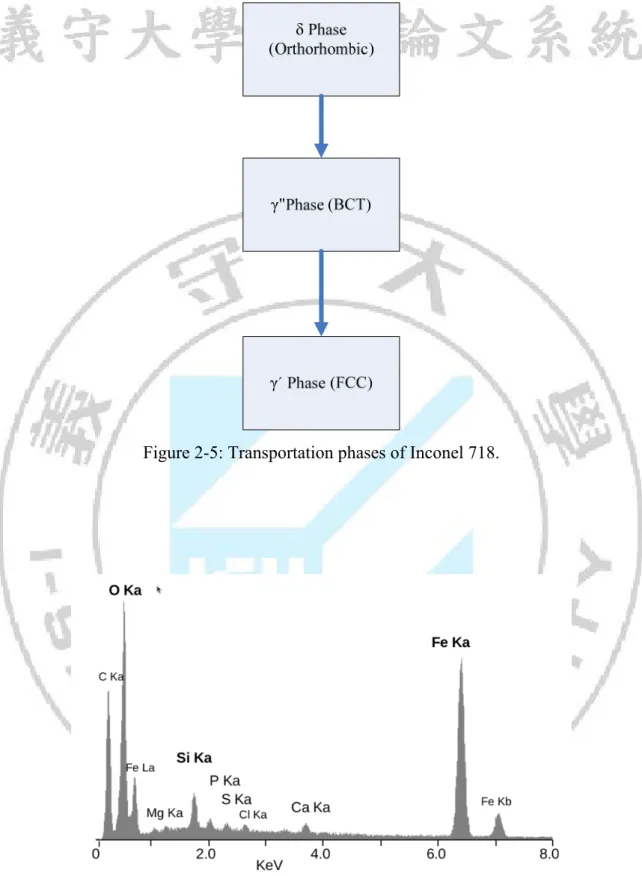
(18) phase[17], is shown in Figure 2-2. Although the δ-phase at high temperatures can prevent grain boundary movement, so that the grain is difficult to grow[18], the amount of precipitation will also reduce the strength of Inconel 718. 2.2.5 Carbides Carbon, added at levels of about 0.05%~0.2% combines with reactive and refractory elements such as titanium, tantalum, and hafnium to form MC carbides[19]. M represents the majority of titanium (Ti), niobium (Nb), tantalum (Ta), hafnium (Hf), zirconium (Zr), and thorium (Th). MC carbide of Inconel 718 is the usual form of carbon, mainly composed of TiC and NbC[20], of which the TiC carbide is more stable. MC-type carbides exist in the grain and grain boundaries, with enhanced performance characteristics. A small amount of carbide precipitation at grain boundaries can limit the grain growth at high temperatures[21] to prevent the phenomenon of grain boundary sliding and can increase the alloy strength and ductility.. 2.3 Effect of Heat Treatment on the Precipitate Phases Inconel-718 nickel-base superalloy was subjected to a heat treatment experiment, focusing on the impact of sustained high and low temperatures. Solution and aging treatment were carried out using the relationship between temperature and time, as shown in Figure 23[22] and Figure 2-4[23], from which the existence and the scope of the various precipitates can be known. Accordingly a typical solid-melting temperature of 980°C was held for 1 hour[24], and later the solution temperature was fixed at 1032° C. By this way γ', γ" and δ effectively dissolve back to the matrix, but the lave phase is still not effectively dissolved. Both solid solution and aging treatments are required to obtain the maximum heat treatment effects. Typical solid solution treatment temperature is 1095°C, which solves carbides and lave phases back to the matrix. Aging treatment was firstly conducted at 955°C to precipitate δ phase, then secondly at 720°C and finally at 620°C to precipitate γ′ and γ″ phases as shown in Figure 2-5.. 2.4 Principles of Electron Energy Dispersive X-ray Spectroscopy Energy dispersive X-ray spectroscopy (EDS/EDX)[25] is an analytical technique used for the elemental analysis or chemical characterization of a sample. It is one of the variants of XRF. As a type of spectroscopy, it relies on the investigation of a sample through interactions between electromagnetic radiation and matter, analyzing X-rays emitted by the matter in response to being hit with charged particles. Its characterization capabilities are due in large part to the fundamental principle that each element has a unique atomic structure allowing xrays that are characteristic of an element’s atomic structure to be identified uniquely from 8.
(19) each other. To stimulate the emission of characteristic X-rays from a specimen, a high energy beam of charged particles such as electrons or protons or a beam of X-rays is focused into the sample being studied. At rest, an atom within the sample contains ground state (or unexcited) electrons in discrete energy levels or electron shells bound to the nucleus. The incident beam may excite an electron in an inner shell, ejecting it from the shell while creating an electron hole where the electron was. An electron from an outer, higher-energy shell then fills the hole, and the difference in energy between the higher-energy shell and the lower energy shell may be released in the form of an X-ray. The number and energy of the X-rays emitted from a specimen can be measured by an energy dispersive spectrometer. As the energy of the X-rays are characteristic of the difference in energy between the two shells, and of the atomic structure of the element from which they were emitted, this allows the elemental composition of the specimen to be measured as shown in Figure 2-6.. 2.5 Creep Definition High temperature progressive deformation of a material at constant stress is called [26]. creep. . High temperature is a relative term that is dependent on the materials being. evaluated. A typical creep curve is shown in Figure 2-7. In a creep test a constant stress is applied to a tensile specimen maintained at a constant temperature. Strain is then measured over a period of time. The slope of the curve, identified in the Figure 2-7, is the strain rate of the test during stage II or the creep rate of the material. Temperature control is critical to minimize the effects of thermal expansion on the sample. Creep is generally divided into three stages: Stage I: Primary creep, Stage I, is a period of decreasing creep rate. Primary creep is a period of primarily transient creep. During this period deformation takes place and the resistance to creep increases until stage II. Stage II: Secondary creep, Stage II, is a period of roughly constant creep rate. Stage II is referred to as steady state creep. Stage III: Tertiary creep, Stage III, occurs when there is a reduction in cross sectional area due to necking or effective reduction in area due to internal void formation.. 9.
(20) (a). (b). Figure 2-1: (a) FCC γ' structure, (b) BCT γ" structure[15].. Figure 2-2: Volume fraction and aging time relationship between γ" and δ phases[17].. 10.
(21) Figure 2-3: Solid solution and the effect of temperature diagram[22].. Figure 2-4: The temperature range for the existence of precipitates of Inconel 718[23].. 11.
(22) Figure 2-5: Transportation phases of Inconel 718.. Figure 2-6: Elemental Energy dispersive X-ray microanalyses of the mineral crust of Rimicaris exoculata.. 12.
(23) Figure 2-7: Creep strain versus time graph.. 13.
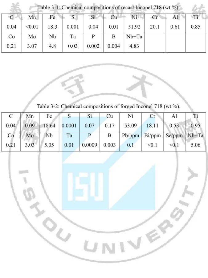
(24) CHAPTER III EXPERIMENTAL PROCEDURES 3.1 Experimental Materials Round bar Inconel 718 superalloy with diameter 8.3 mm was chosen as the test material (recast specimen), which was recast by Chung-Shan Institute of Science and Technology, Taiwan. The chemical compositions are according to AMS-5383 standard as shown in table 3-1. The other round bar Inconel 718 superalloy with diameter 11 mm was also chosen as the test material (forged specimen), which was molten by the DUVAC (VIM and VAR) processes. The chemical analysis performed by Huntington Alloys, West Virginia, is shown in table 3-2.. 3.2 Heat Treatment Process From the Time-Temperature-Transformation[27] (TTT) diagram of Inconel 718 superalloy shown in Figure 3-1, the temperature distribution of various precipitates can be seen in general foundry. The first implementation of the solution treatment was to heat Inconel 718 superalloy to 1095° C and hold this temperature for 1 hour to allow all kinds of precipitates and laves back to the matrix. Upon completion of the heat treatment the sample was removed and air-cooled (air cooling) to room temperature. The sample was then heated to 955°C, held for 1 hour and then removed and air-cooled to room temperature, to let δ-phase precipitates occur. Finally, a double ageing process was carried out for the test piece, the sample was heated at 720°C for 8 hours, and then furnace cooled at a rate of 57K/h to 620°C for 8 hours. After which the sample was air-cooled to room temperature[28]. The complete heat treatment process is shown in Figure 3-2. The heat treatment furnace using in this thesis is shown in Figure 3-3.. 3.3 Rockwell Hardness Testing Rockwell hardness testing[29] is a general method for measuring the bulk hardness of metallic and polymer materials. Although hardness testing does not give a direct measurement of any performance properties, hardness of a material correlates directly with its strength, wear resistance, and other properties. Hardness testing is widely used for material evaluation because of its simplicity and low cost relative to direct measurement of many properties. Specifically, conversion charts from Rockwell hardness to tensile strength are available for some structural alloys, including steel and aluminum. A high quality Rockwell type hardness tester DXT-3 by Matsuzawa Seiki Co., Ltd., Tokyo, Japan, was used to measure the hardness.. 14.
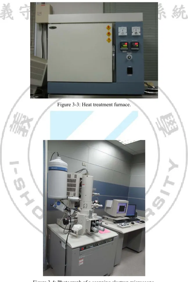
(25) 3.4 Grain Size Measurement A direct approach of assessing the grain size of a material would be to determine the actual average grain diameter[30]. This offers clear advantages to the ASTM grain-size number that in reality does not offer any direct information about the actual size of the grain. In this approach, once a photomicrograph is prepared at a specific magnification, a random line of known length is drawn on the photomicrograph. The number of grains to the actual length of the line is determined, nL. The average grain diameter D is determined using the equation, D = C/ nL M where C is a constant (C = 1.5 for typical microstructures) and M is the magnification at which the photomicrograph is taken.. 3.5 SEM Observation In this technique the surface of a small sample of Inconel 718 superalloy is first prepared through a detailed and rather lengthy procedure. The preparation process includes numerous surface grinding stages (usually eight) that remove large scratches and thin plastically deformed layers from the surface of the specimen. The grinding stage is followed with a number of polishing stages (usually eight: Sequentially from several numbers sandpaper 240, 400, 600, 800, 1000, 1200 number, 2000 number, and finally grinding to a maximum of 2500 number) that remove fine scratches formed during the grinding stage. The quality of the surface is extremely important in the outcome of the process, and generally speaking, a smooth, mirror-like surface without scratches must be produced at the end of the polishing stage to complete the polishing process. These steps are necessary to minimize topographic contrast. The polished surface is then exposed to chemical etchants. The choice of the etchant and the etching time (the time interval in which the sample will remain in contact with the etchant) are two critical factors that depend on the specific material under study, this experiment using the etching solution formula (50% HCl, 10% HNO3, 2% HF, 38% distill water) for 1-2 minutes. The atoms at the grain boundary will be attacked at a much more rapid rate by the etchant than those atoms inside the grain. This is because the atoms at the grain boundary possess a higher state of energy because of the less efficient packing. As a result, the etchant produces tiny groves along the boundaries of the grains. A Hitachi-4700 field-emission scanning electron microscope equipped with a Horiba energy-dispersive X-ray spectrometry (EDX) system was used to examine the microstructure as shown in Figure 3-4.. 15.
(26) 3.6 High Temperature Creep Test In order to carry out high-temperature creep experiments, stress rupture tests were performed using an ATS (Applied test systems, Inc) series 2330 lever arm creep tester as shown in Figure 3-5. Test temperature and stress were 650ºC and 625 MPa, respectively. According to the dimensions of ASTM E8[31] round bar specimens with gage length 1.0 inch (25.4 mm) were machined to the diameter of 0.25 inch (6.35 mm) as shown in Figure 3-6. The role of the test is to balance the principle of leverage in order to achieve a fixed stress effect. The high-temperature furnace is a three-point thermocouple set up on the gauge length of the trial bar to precisely control the temperature, with a temperature error range of ±0.1ºC.. 16.
(27) Table 3-1: Chemical compositions of recast Inconel 718 (wt.%). C. Mn. Fe. S. Si. Cu. Ni. Cr. Al. Ti. 0.04. <0.01. 18.3. 0.001. 0.04. 0.01. 51.92. 20.1. 0.61. 0.85. Co. Mo. Nb. Ta. P. B. Nb+Ta. 0.21. 3.07. 4.8. 0.03. 0.002. 0.004. 4.83. Table 3-2: Chemical compositions of forged Inconel 718 (wt.%). C. Mn. Fe. S. Si. Cu. Ni. Cr. Al. Ti. 0.04. 0.09. 18.64. 0.0001. 0.07. 0.17. 53.09. 18.11. 0.53. 0.95. Co. Mo. Nb. Ta. P. B. 0.21. 3.03. 5.05. 0.01. 0.0009. 0.003. Pb/ppm Bi/ppm Se/ppm Nb+Ta. 17. 0.1. <0.1. <0.1. 5.06.
(28) Figure 3-1: the TTT diagram of Inconel 718[27].. Figure 3-2: Heat treatment scheme.. 18.
(29) Figure 3-3: Heat treatment furnace.. Figure 3-4: Photograph of a scanning electron microscope.. 19.
(30) Figure 3-5: ATS series 2330 lever arm creep tester.. Figure 3-6: Creep test specimen specifications.. 20.
(31) CHAPTER IV RESULTS AND DISCUSSTIONS 4.1 OM Observation The average grain size of recast Inconel 718 superalloy is much greater than that of forged one for about 20 times as shown in table 4-1. The huge grain size of recast Inconel 718 superalloy supposedly has a beneficial effect on the creep behavior. The cross sectional image of recast Inconel 718 superalloy is shown in Figure 4-1. Using the optical microscope (OM) to observe the microstructure, a large number of porosities are found in the recast Inconel 718 superalloy specimens as shown in Figure 4-2.. 4.2 SEM observation and EDX Typical SEM micrographs showing carbides of as-received material of recast and forged Inconel 718 are shown in Figures 4-3 and 4-4[28], respectively. EDX analyzer system is used to identify composition elements of the carbide precipitates as shown in Figures 4-5 and 4-6[28]. EDX results identify that NbC type carbide for both recast and forged Inconel 718 superalloys as shown in table 4-2. Using SEM to observe the microstructure of as-received materials, a large number of porosities are found in the recast Inconel 718 superalloy specimens as shown in Figure 4-7. After heat treatment, the average grain size of both recast and forged Inconel 718 is growing and most of the carbides are dissolved back to the matrix, however, there are still some left as shown in Figures 4-8 and 4-9[28]. The energy dispersive X-ray analyzer system is used to identify composition elements as shown in Figures 4-10 and 4-11[28]. EDX results identify that NbC type carbide precipitate for both recast and forged Inconel 718 superalloys as shown in table 4-3. Some of the carbides are located inside the grain and along the grain boundary of recast Inconel 718 superalloy. Carbide morphology is very long, which along the grain boundary has harmful effect on the mechanical properties. After heat treatment, a large number of porosities are also found in the recast Inconel 718 superalloy specimens as shown in Figure 4-12.. 4.3 Rockwell Hardness Measurement In the present study, HRC specifications are chosen for Rockwell Hardness test. Nine hardness measurements located at specific positions as shown in Figure 4-13 are used to obtain the average hardness value. After heat treatment the average hardness value of recast Inconel 718 superalloy is 37.75 HRC as shown in table 4-4, which is similar to the forged Inconel 718 superalloy as shown in table 4-5. Hardness value is mainly due to both γ′ and γ″ 21.
(32) precipitates. The amounts are γ″ and γ′ precipitates, together with their shape and distribution, have a determining influence on the mechanical properties.. 4.4 Porosity Using the OM/ SEM to observe the microstructure, a large number of porosities are found in the recast Inconel 718 superalloy specimens as shown in Figures 4-2, 4-7, 4-12 and 4-15. Average porosity size and percentage are 24.7 μm and 2.683%, respectively, as shown in table 4.6. The average porosity size can be classified as meso-porosity. The percentage porosity is very high that has mainly harmful effects on creep behavior.. 4.5 High Temperature Creep Behavior After the same heat treatment, the creep curves between two kinds of Inconel 718 are shown in Figure 4-14. The creep rupture life time of forged Inconel 718 is (about 1800 hours) much longer than that of recast Inconel 718 (about 120 hours). SEM fractographs of crept specimens are shown in Figures 4-15 and 4-16 for recast and forged specimens, respectively. Since the average porosity size and percentage are very high in the recast Inconel 718 specimens, porosity is the main reason to lead to premature creep rupture failure. Fracture of a recast Inconel 718 crept specimen by rapid crack propagation through the porosities is shown in Figure 4-17. Conversely, because the grain boundaries are the weak areas in the forged Inconel 718 superalloy, SEM fractographs indicate inter-granular fracture pattern as shown in Figure 4-16. The inter-granular facture of a forged Inconel 718 crept specimen occurs by slow crack propagation as shown in Figure 4-18.. 22.
(33) Table 4-1: The average grain size. Materials. Average Grain size (µm). Inconel 718 (Recast). 3392±68. Inconel 718 (Forged). 170±12.88. Table 4-2: Composition elements of carbide by EDX for as-received materials (Atomic %). Element. Recast Inconel 718. Forged Inconel 718. C. 49.74. 55.97. Al. 0.03. 0.14. Ti. 0.39. 4.20. V. 0.07. -. Mn. -0.31. -. Fe. 6.56. 0.79. Co. 0.12. -. Ni. 20.94. 1.12. Cu. 0.13. -. Nb. 10.45. 36.50. Mo. 2.99. 0.17. W. 0.07. -. Si. 0.65. 0.28. Cr. 8.18. 0.84. Totals. 100.00. 100.00. 23.
(34) Table 4-3: Composition elements of carbide by EDX after heat treatment (Atomic %). Element. Recast Inconel 718. Forged Inconel 718. C. 49.43. 60.83. Al. -0.15. -0.09. Ti. 6.33. 5.49. V. 0.08. -. Mn. 0/02. -. Fe. 0.42. 0.37. Co. -0.58. -. Ni. 2.17. 1.36. Cu. -0.35. -. Nb. 42.85. 30.38. Mo. -0.02. 0.42. W. -0.21. -. Si. -. 0.17. Cr. -. 0.63. Totals. 100.00. 100.00. 24.
(35) Table 4-4: Hardness values of recast Inconel 718 after heat treatment at nine test locations (HRC). Locations. Average Hardness Value. A. 36.4. B. 38.0. C. 37.2. D. 36.6. E. 38.3. F. 38.0. G. 36.7. H. 40.6. J. 38.0. Average. 37.75. Table 4-5: Rockwell hardness value for two kinds of Inconel 718 superalloys (HRC). Materials. Average Hardness Value. Recast Inconel 718. 37.75. Forged Inconel 718. 38.72. Table 4-6: Average porosity size and percentage of recast Inconel 718. Process Recast. Average porosity size. Percentage porosity. (µm). (%). 24.7. 2.683. 25.
(36) Figure 4-1: Cross sectional view of a recast Inconel 718 specimen after heat treatment.. 26.
(37) (a). (b) Figure 4-2: Optical Microscope pictures showing porosities of a recast Inconel 718 specimen, (a) 200X, (b) 500X.. 27.
(38) Figure 4-3: SEM image showing carbides of as-received recast Inconel 718.. Figure 4-4: SEM image showing carbides of as-received forged Inconel 718[28].. 28.
(39) Figure 4-5: SEM image with EDX position showing carbides of as-received recast Inconel 718.. Figure 4-6: SEM image with EDX position showing carbides of as-received forged Inconel 718 [28].. 29.
(40) (a). (b) Figure 4-7: SEM images showing porosity of original material recast Inconel 718, (a) 50X, (b)100X.. 30.
(41) Figure 4-8: SEM image showing carbides of recast Inconel 718 after heat treatment.. Figure 4-9: SEM image showing carbides of Forged Inconel 718 after heat treatment[28].. 31.
(42) Figure 4-10: SEM image with EDX position showing carbides of recast Inconel 718 after heat treatment.. Figure 4-11: SEM image with EDX position showing carbides of forged Inconel 718 after heat treatment [28].. 32.
(43) (a). (b) Figure 4-12: : SEM images showing porosity of recast Inconel 718 after heat treatment, (a) 50X, (b) 250X.. 33.
(44) Figure 4-13: Hardness testing locations of a specimen cross section.. 34.
(45) 16. Creep Strain (%). 14. Recast. 12. Forged. 10 8 6 4 2 0 0. 200. 400. 600. 800. 1000 1200 1400 1600 1800. 2000. Time (h) Figure 4-14: Creep curves of recast and forged Inconel 718 specimens under constant tensile stress 625 MPa at 650°C.. 35.
(46) (a). (b) Figure 4-15: SEM fractographs of a crept recast Inconel 718 specimen, (a) 50X, (b) 80X.. 36.
(47) (a). (b) Figure 4-16: SEM fractographs of a crept forged Inconel 718 specimen, (a) 100X, (b) 300X.. 37.
(48) Figure 4-17: Fracture surface of a crept recast Inconel 718 specimen shows rapid crack propagation.. Figure 4-18: Fracture surface of a crept forged Inconel 718 specimen shows slow crack propagation.. 38.
(49) CHAPTER V CONCLUSIONS The important results of this study can be concluded as follows: 1. The mechanical properties are very much dependent on the microstructures and material processes. Through the use of OM and SEM, the microstructure was observed; this experiment explored a large number of porosities in recast Inconel 718 superalloy. 2. The average grain size of recast Inconel 718 superalloy is much greater than that of forged one for about 20 times 3. Hardenbility depends on the sum of strengthening phases γ'/γ" precipitated.. The. precipitation hardenings are γ′ and γ″ precipitates exist to improve hardness. 4. The creep rupture life of forged Inconel 718 (about 1800 hours) is much longer than that of recast Inconel 718 (about 120 hours). 5. Average porosity size and percentage are 24.7 μm and 2.683%, respectively, in the recast Inconel 718 superalloy, which have main harmful effect on the creep rupture life.. 39.
(50) REFERENCES [1]. http://www.fiddlersgreen.net/models/aircraft/Heinkel-178.html. [2]. http://en.wikipedia.org/wiki/Ernst_Heinkel. [3]. R. C. Reed, The Superalloys Fundamentals and Application, Cambridge University Press, New York, NY, USA, 2006, p. 3.. [4]. C. T. Sims and W. C. Hagel (Eds.), The superalloys, John Wiley & Sons, New York, USA, 1972, p. 5.. [5]. C. T. Sims, N. S. Stoloff and W. C. Hagel (Eds.), Superalloys II, John Wiley & Sons, New York, USA, 1987, p. 3.. [6]. M. J. Donachie and S. J. Donachie, Superalloys A Technical Guide, second edition, ASM International, USA, OH, 2002, p. 9.. [7]. R. C. Reed, The Superalloys Fundamentals and Applications, Cambridge University Press, Cambridge, UK, 2006, p. 3.. [8]. G. A. Rao, M. Kumar, M. Srinivas and D. S. Sarma, “Effect of standard heat treatment on the microstructure and mechanical properties of hot isostatically pressed superalloy Inconel 718,” Materials Science and Engineering, vol. 355, pp. 114–125, 2003.. [9]. S. Azadian, L. Y. Wei and R. Warren, “Delta phase precipitation in Inconel 718,” Materials Characterization, vol. 53, pp. 7–16, 2004.. [10] G. D. Smith and S. J. Patel, “The role of niobium in wrought precipitation-hardened nickel-base alloys,” Proceedings of the Sixth International Symposium on Superalloys 718, 625, 706 and Derivatives, E. A. Loria (Ed.), TMS, Pittsburgh, PA, USA, pp.149-155, 2005. [11] L. Xiao, D. L. Chen and M. C. Chaturvedi, “Effect of Boron on the Low Cycle Fatigue Behavior and Deformation Structure of Inconel 718 at 650ºC,” Metallurgical and Materials Transactions A, vol. 35A, pp. 34773487, 2004. 40.
(51) [12] W. R. Sun, S. R. Guo, D. Z. Lu and Z. O. Hu, “Effect of Sulfur on the Solidification and Segregation in Inconel 718 alloy,” Materials Letters, vol. 31, pp. 195-200, 1997. [13] H. Song, S. Guo and Z. Hu, “Beneficial effect of phosphorus on the creep behavior of Inconel 718,” Scripta Materialia, vol. 41, pp. 215-219, 1999. [14] C. Slama and M. Adbellaoui, “Structural characterization of the aged Inconel 718,” Journal of Alloys and Compounds, vol. 306, pp. 277-284, 2000. [15] C. T. Sims, N. S. Stoloff and W. C. Hagel (Eds.), Superalloys II, John Wiley & Sons, New York, USA, 1987, p. 177. [16] L. Liu, C. Zhai, C. Lu, W. Ding, A. Hirose and K. F. Kobayashi, “Study of the effect of δ phase on hydrogen embrittlement on Inconel 718 by notch tensile tests,” Corrosion Science, vol. 47, pp. 355-367, 2005. [17] H. Yuan and W. C. Liu, “Effect of δ phase on the hot deformation behavior of Inconel 718,” Materials Science and Engineering A, vol. 408, pp. 281-289, 2005. [18] S. Li, J. Zhuang, J. Yang, Q. Deng and J. Du, “The effect of δ-phase on crack propagation under creep and fatigue conditions in alloy 718,” in Superalloys 718, 625, 706 and Various Derivatives, E. A. Loria (Ed.), TMS, Pittsburgh, PA, USA, pp. 545-555, 1994. [19] M. J. Donachie and S. J. Donachie, superalloys A Technical Guide, second edition, ASM International, OH, 2002, p. 27. [20] A. Thomas, M. El-Wahabi, J. M. Cabrera and J. M. Prado, “High temperature deformation of Inconel 718,” Journal of Materials Processing Technology, vol. 177, pp. 469-472, 2006. [21] S. Azadian, L. Y. Wei and R. Warren, “Delta phase precipitation in Inconel 718,” Materials Characterization, vol. 53, pp. 7-16, 2004 [22] C. T. Sims and W. C. Hagel (Eds.), The Superalloys, John Wiley and Sons, New York, USA, 1972, p. 133. 41.
(52) [23] C. T. Sims, N. S. Stoloff and W. C. Hagel (Eds.), Superalloys II, John Wiley & Sons. New York, USA, 1987, p. 186. [24] M. J. Donachie and S. J. Donachie, superalloys A Technical Guide, second edition, ASM International, OH, 2002, p. 140. [25] http://en.wikipedia.org/wiki/Energy-dispersive_X-ray_spectroscopy. [26] http://www.materialsengineer.com/CA-Creep-Stress-Rupture.htm. [27] A. O. Basile and J. F. Radavich, “A current T-T-T diagram for wrought alloy 718,” in Superalloys 718, 625, and Various Derivatives, E. A. Loria (Ed.), TMS, Pittsburgh, PA, USA, pp. 325-335, 1991. [28] C.-C. Tai, Heat treatment of Inconel 718 superalloy, Master thesis, Department of Mechanical and Automation Engineering, I-Shou University, Kaohsiung, Taiwan, August, 2007. [29] http://mee-inc.com/rockhar.html. [30] W. F. Smith and J. Hashemi, Foundations of Materials Science and Engineering, 4th edition, McGraw Hill, New York, NY, USA, 2006, p.155. [31] ASTM E 8/8M, “Standard Test Methods for Tension Testing of Metallic Materials,” Annual Book of ASTM Standards, vol. 03.01.. 42.
(53)
數據
![Figure 4-4: SEM image showing carbides of as-received forged Inconel 718 [28] . ..........................................................................................................](https://thumb-ap.123doks.com/thumbv2/9libinfo/8959171.277110/9.892.96.788.326.934/figure-sem-image-showing-carbides-received-forged-inconel.webp)
![Figure 1-1: An old photo of the Heinkel He-178 world’s first jet aircraft [1] .](https://thumb-ap.123doks.com/thumbv2/9libinfo/8959171.277110/13.892.117.770.94.1005/figure-old-photo-heinkel-world-s-jet-aircraft.webp)
![Figure 1-3: The engine to withstand both temperature and pressure [4] .](https://thumb-ap.123doks.com/thumbv2/9libinfo/8959171.277110/14.892.118.772.96.1017/figure-engine-withstand-temperature-pressure.webp)
+7
![Figure 2-3: Solid solution and the effect of temperature diagram [22] .](https://thumb-ap.123doks.com/thumbv2/9libinfo/8959171.277110/21.892.120.774.102.932/figure-solid-solution-effect-temperature-diagram.webp)

![Figure 3-1: the TTT diagram of Inconel 718 [27] .](https://thumb-ap.123doks.com/thumbv2/9libinfo/8959171.277110/28.892.121.783.100.992/figure-ttt-diagram-inconel.webp)
相關文件
To investigate the characteristic of HfZrO x used a gate dielectric, we measured the gate leakage current, mobility and transistor performance.. Therefore,
This study aimed to establish the strength models of High-Performance Concrete (HPC) at different ranges of water binder ratio (W/B) using Genetic Operation Trees (GOT),
Using the DMAIC approach in the CF manufacturing process, the results show that the process capability as well as the conforming rate of the color image in
The purposes of this series studies were to investigate difference between batting performance at peak level and slump level in visual cue strategy, dynamic
By using Balanced Scorecard (BSC), the purpose of this study is to construct indicators of school management with Analytic Hierarchy Process (AHP) for L junior high school in
In this study, teaching evaluation were designed to collect performance data from the experimental group of students learning with the “satellite image-assisted teaching
The purpose of this study is to investigate the researcher’s 19 years learning process and understanding of martial arts as a form of Serious Leisure and then to
In this study, we report the preparation of metal Zinc (Zn) and Zinc oxide (ZnO) nanoparticles using an evaporation/condensation aerosol process via horizontal tube furnace
