國立臺灣大學高分子科學與工程學研究所 碩士論文
Institute of Polymer Science and Engineering College of Engineering
National Taiwan University Master Thesis
應用於光電元件之高性能電致變色材料及導電材料之 合成、製備及性質探討
Synthesis, Preparation, and Characterization of High-Performance Electrochromic and Conductive
Materials for Optoelectronic Devices 劉桓升
Huan-Shen Liu
指導教授:劉貴生 博士
Advisor: Guey-Sheng Liou, Ph.D.
中華民國 105 年 7 月
July, 2016
ACKNOWLEDGEMENTS
I would like to express sincere appreciation to the advisor, Professor Guey-Sheng Liou, for his tireless instruction, professional knowledge, and patient guidance throughout this thesis, preparation of the manuscript. Besides, I would also like to thank to my committees: Professor Sheng-Huei Hsiao, Tzong-Ming Lee and Yu-Ruei Kung for their useful suggestions provided this study more complete and all teachers at Institute of Polymer Science and Engineering in the National Taiwan University.
I also shows appreciation to Chia-Liang Tsai, Jia-Hao Wu, Chin-Yen Chou, Bo-Cheng Pan, Shun-Wen Cheng, Dai-Ni Hsieh, Yang-Ze Fan, Jung-Tsu Wu and all friends of mine for their continuous encouragement and constant supports.
I thank the Institute of Polymer Science and Engineering at the National Taiwan University for providing a congenial environment for my graduate studies. A financial supports from the Ministry of Science and Technology of the Republic of China is also greatly appreciated.
Finally, I express my deepest love and gratitude to my family for their concern and support during the period of study. All my achievements have been possible only because of their support, love and encouragement.
ABSTRACT
This study has been separated into four chapters. Chapter 1 is the general introduction. Chapter 2 includes the synthesis of electrochromic materials (ECMs) and fabrication of high contrast electrochromic devices (ECDs). Chapter 3 describes the preparation of stretchable electrodes based on silver nanowires (AgNWs) and polydimethylsiloxane (PDMS) hybrid for elastomeric ECDs. Chapter 4 is conclusions.
The fabrication, basic characterization, electrochromic properties of a novel ECD was investigated and improved. The ECD combined three different kinds of ECMs, TPPA-PA, TPB-PA and HV. By introducing HV as an efficient charge trapping layer, the working voltage could be greatly reduced and the performance of overall system was also enhanced. The ECD of Blending-A system exhibits ultra-high contrast from bleaching state with transmittance in visible region up to 85% to coloring state with transmittance only 6% both in visible and NIR regions. High ΔL* (88.2) and ΔT (79.0% at visible light region) could be achieved by the colorless ECD. Thus, it could claim to be a truly “transmissive-to-black” ECD, implying high potential of application as shutter for transparent displays and energy saving devices.
In another part, an effective method to transfer AgNWs into PDMS by sacrificial substrates which has hydrophobic surface, and successfully prepare stretchable AgNWs/PDMS hybrid electrodes having high transparency and low sheet resistance at the same time. The prepared electrodes could be stretched, twisted, and bended without significant loss of conductivity. Furthermore, a novel elastomeric HV ECD was fabricated based on these stretchable AgNWs/PDMS hybrid electrodes. This elastomeric HV ECD could exhibit excellent electrochromic behavior and transform the color between colorless and blue even after 100 switching cycle. It was the first ECD based on full AgNWs system.
中文摘要
本論文分成四個章節,第一章為總體序論。第二章為高對比度雙極式電致變色 元件之製備,此元件以 TPPA 及 TPB 為變色中心的聚醯胺及紫精衍生物分別為 陽極和陰極變色材料,讓陽極及陰極變色材料作為互相之電荷儲存基層,達到穩 定及降低工作電壓的效果,並藉由三種材料在 UV-Vis 吸收光譜上的互補,使可 見光區吸收完全,達到全波段遮蔽之效果。第三章是以簡易及方便的方式製備透 明可拉伸電極進行電致變色元件的應用。第四章節為結論。此研究探討應用於光 電元件中之電致變色材料的搭配及導電材料的製程改進,所製備出的雙極式電致 變色元件在透明態時具有高度的透明性,而在著色態時展現紫外光-可見光-近紅 外光區全光譜吸收的優異結果,並在長時間使用下仍具有良好的穩定性。此外,
以簡易方法轉印奈米銀線至聚二甲基矽氧烷基材所製備出的可拉伸複材電極,同 時具備高透明性及高導電度,且在拉伸、扭轉及彎曲情形下仍具有導電性,而我 們由此可拉伸複材電極進一步製備出彈性電致變色元件,在透明態及著色態的切 換也展現出良好的穩定性。
TABLE OF CONTENTS
ACKNOWLEDGEMENTS………I
ABSTRACT (in English)....……….…….…..………...II
ABSTRACT (in Chinese)………….………....III
TABLE OF CONTENTS……….………..………….…IIV
LIST OF TABLES……….………...…...IX
LIST OF FIGURES………..X
CHAPTER 1………...1
CHAPTER 2……….81
CHAPTER 3………...122
CHAPTER 4………...153
CHAPTER 1 General Introduction
1.1 HIGH PERFORMANCE POLYMERS ... 2
1.1.1 Preparation of Aromatic Polyamides ... 4
1.1.1-1 High-temperature solution method ... 4
1.1.1-2 Low-temperature solution method ... 6
1.1.2 Preparation of Aromatic Polyimides ... 7
1.1.3 Modification of Aromatic Polyamides and Polyimides ... 9
1.2 ELECTROCHROMISM ... 13
1.2.1 Electrochromic Systems ... 17
1.2.1-1 Transition-metal Oxides ... 17
1.2.1-2 Inorganic Coordination Complexes ... 18
1.2.1-3 Organic Molecules ... 20
1.2.1-4 Conducting Polymers ... 23
1.2.1-5 Arylamine-based Polymers ... 25
1.2.2 The Structure of Electrochromic Device ... 28
1.2.2-1 Transparent conducting layer ... 28
1.2.2-2 Electrochromic layer ... 28
1.2.2-3 Electrolyte layer ... 28
1.2.2-4 Ion-storage layer ... 29
1.2.3 High Contrast Electrochromic Devices ... 30
1.3 TRANSPARENT CONDUCTIVE ELECTRODES ... 32
1.3.1 Transparent and Conductive Material ... 35
1.3.1-1 Doped Metal Oxides ... 36
1.3.1-2 Conducting Polymers ... 37
1.3.1-3 Carbon Nanostructures ... 38
1.3.1-4 Metallic Nanostructures ... 41
1.3.2 Silver Nanowires (AgNWs) ... 42
1.3.2-1 Growth mechanism of polyol method ... 43
1.3.2-2 Synthetic factors of AgNW ... 43
1.3.3 AgNWs/ Polymer Hybrid Transparent Electrodes ... 46
1.3.3-1 Aspect ratio of AgNWs ... 46
1.3.3-2 Pre-treatments ... 46
1.3.3-3 Coating methods ... 47
1.3.3-4 Post-treatments ... 47
1.3.4 Protection of AgNWs ... 54
1.4 RESEARCH MOTIVATION ... 56
REFERENCES AND NOTES ... 59
CHAPTER 2
Highly Transparent to Truly Black Electrochromic Devices Based on Ambipolar System of Polyamides and Viologen
ABSTRACT ... 82
2.1 INTRODUCTION ... 83
2.2 EXPERIMENT SECTION ... 86
2.2.1 Materials ... 86
2.2.2 Polymer synthesis ... 88
2.2.3 Fabrication of the Electrochromic Devices ... 92
2.2.4 Characterization ... 93
2.3 RESULT AND DISCUSSION ... 94
2.3.1 Basic Properties of Polyamides ... 94
2.3.2 Electrochemical Properties of the ECMs ... 99
2.3.3 Electrochemical Properties of the ECDs ... 101
2.3.4 Spectroelectrochemistry ... 104
2.3.5 Materials Integration ... 108
2.3.6 Thickness Effects ... 111
2.3.7 Chemical Structure Effects ... 113
2.4 SUMMARY ... 118
REFERENCES AND NOTES ... 119
CHAPTER 3
Highly Transparent Silver Nanowires/ Polydimethylsiloxane Electrode for Elastomeric Electrochromic Device
ABSTRACT ... 123
3.1 INTRODUCTION ... 124
3.2 EXPERIMENT SECTION ... 126
3.2.1 Materials ... 126
3.2.2 Silver nanowires synthesis ... 126
3.2.3 AgNWs-PDMS stretchable electrode fabrication ... 127
3.2.4 Elastomeric electrochromic device fabrication ... 128
3.2.5 Characterization ... 129
3.3 RESULT AND DISCUSSION ... 130
3.3.1 Basic characterization ... 130
3.3.2 Properties of flexible and transparent AgNWs/PDMS hybrid electrodes ... 133
3.3.3 Stretching, twisting, and bending behavior of the transparent AgNWs/PDMS hybrid electrodes ... 137
3.3.4 Properties of Elastomeric Electrochromic Device ... 142
3.4 SUMMARY ... 149
REFERENCES AND NOTES ... 150
LIST OF TABLES
CHAPTER 1
Table 1.1 Some Typical Aromatic High Performance Polymers ... 3
Table 1.2 Commercially Available Aromatic Polyamides ... 6
Table 1.3 Commercially Available Aromatic Polyimides ... 9
Table 1.4 Some Soluble Aromatic Polyamides ... 11
Table 1.5 Some Soluble Aromatic Polyimides ... 12
Table 1.6 Color of viologens based on different substituted structure ... 21
Table 1.7 Color of quinone systems ... 22
Table 1.8 The advantages and drawbacks of conducting polymer ... 24
Table 1.9 Publish papers. (Web of Science. Key word: transmissive-to-black) ... 31
Table 1.10 List of various applications, their key features, and the suitability of each material ... 34
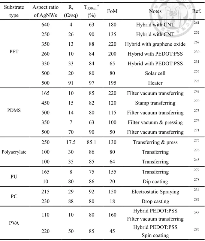
Table 1.11 Examples and comparisons for AgNWs-polymer hybrid systems ... 51
Table 1.12 A partial list of performance of AgNWs-PI films reported in literatures 53 CHAPTER 2 Table 2.1 Inherent Viscosity and Molecular Weights of Polyamides ... 95
Table 2.2 Solubility Behaviors of Polyamides ... 95
Table 2.3 Thermal Properties of Polyamides ... 96
CHAPTER 3 Table 3.1 Thermal properties of PDMS ... 131
Table 3.2 Solubility Behaviors of PDMS ... 131
Table 3.3 Optical and Electrochemical Data Collected for Coloration Efficiency Measurements of HV ECD based on the AgNWs/PDMS hyvrid electrode ... 148
LIST OF FIGURES
CHAPTER 1
Figure 1.1 Electrochromic products application categories. ... 15 Figure 1.2 Photographs of (a) smart windows (b) anti-glare back mirrors (c) and E-papers. ... 16 Figure 1.3 Switching sequence of the electrochromic glass. ... 16 Figure 1.4 Representative electrochromic polymers. Color swatches are representations of thin films based on measured CIE 1931 Yxy color coordinates.
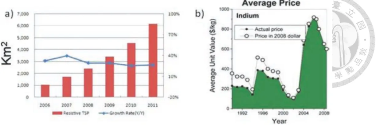
Key: 0 = neutral; I = intermediate; + = oxidized; − and − − = reduced. ... 25 Figure 1.5 High-performance polymers (e.g., polyimide types, polyamide types, and epoxy types) utilizing the triarylamine units as an electrochromic functional moiety.27 Figure 1.6 The schematic of typical ECD structure. ... 29 Figure 1.7 Potential transparent conductive materials applications and corresponding resistance range required for each application. ... 33 Figure 1.8 (a) Global demand for resistive style touch panels by area (Source:
Displaybank “In depth analysis: Touch screen panel industry trends and business strategies”) (b) Average price of Indium over the last several decades (Source: Alex Freundlich of the University of Houston citing data from the U.S. Geological Survey).
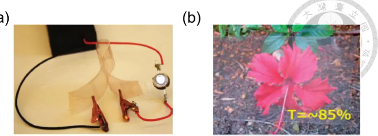
... 34 Figure 1.9 (a) The transparent electrode based on ITO. (b) The s transparent solar cells made by ITO. ... 37 Figure 1.10 (a) The OLED based on conducting polymers. (b) Demonstration of a deformable LED fabricated on a PEDOT:PSS circuit. ... 38 Figure 1.11 (a) The transparent electrode based on CNT.192 (b) The skin-like pressure sensors made by CNT. ... 39 Figure 1.12 The transparent graphene electrode and the application in touch screen.41 Figure 1.13 Demonstration of flexible, transparent films by the combination of (a) copper nanowires,211 and (b) silver nanowires with polymer substrates.134 ... 42
Figure 1.14 The schematic diagram of (a) growing silver nanowires,219 and (b) the
function of oxygen scavenger. ... 45
Figure 1.15 Representative TEM images of titania coated silver nanowires with increasing titania shell thickness: (a) 10, (b) 22, (c) 44, (d) 65 and (e) 85 nm. ... 55
Figure 1.16 Transparent display material market. ... 58
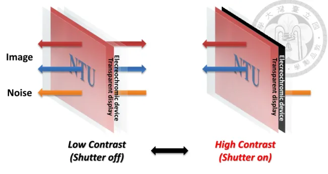
Figure 1.17 Schematic diagram of transparent display based on OLED with ECD as shutter. ... 58
CHAPTER 2 Figure 2.1 Schematic diagram of the transparent display regulated by ECD. ... 85
Figure 2.2 IR spectrum of polyamide films ... 91
Figure 2.3 Schematic diagram of ECD based on the ambipolar ECMs. ... 92
Figure 2.4 TGA traces of the polyamides. ... 97
Figure 2.5 DSC traces of polyamides with a heating rate of 20 °C /min in nitrogen. 98 Figure 2.6 Cyclic voltammetric diagrams of (a) polyamide thin films and (b) HV on the ITO-coated glass substrate (working electrode area: 12 mm × 5 mm, film thickness: 250nm) in 0.1 M TBAP/CH3CN at scan rate of 50 mV s-1. ... 100
Figure 2.7 Cyclic voltammetric diagrams of (a) TPPA-O ECD, (b) TPB-O ECD on the ITO-coated glass substrate (coated area: 25 mm × 20 mm, thickness: 250 nm) in propylene carbonate with lithium tetrafloroborate (LiBF4) as the supporting electrolyte. ECD composition diagrams of (c) TPPA-O ECD, (d) TPB-O ECD. .... 102
Figure 2.8 Cyclic voltammetric diagrams of (a) TPPA-O/HV ECD, (b) TPB-O/HV ECD on the ITO-coated glass substrate (coated area: 25 mm × 20 mm, thickness: 250 nm) in 3 wt% of LiBF4/propylene carbonate electrolyte with HV containing 0.5 mg as the supporting electrolyte. ECD composition diagrams of (c) TPPA-O/HV ECD, (d) TPB-O/HV ECD. ... 103
Figure 2.9 Electrochromic behavior of (a) TPPA-O, (b) TPB-O, (c) TPPA-A, and (d) TPB-A thin film on the ITO-coated glass substrate (coated area: 12 mm × 5 mm, thickness: 250 nm) in 0.1 M TBAP/CH3CN at applied related potentials. ... 106
Figure 2.10 Electrochromic behavior of HV on the ITO-coated glass substrate (working electrode area: 12 mm × 5 mm, concentration: 0.001 M) in 0.1 M TBAP/CH3CN at applied a potential of -0.42 V. ... 106 Figure 2.11 UV-Vis spectra of (a) TPPA-O ECD, (b) TPB-O ECD, (c) TPPA-O/HV ECD, and (d) TPB-O/HV ECD. ... 107 Figure 2.12. Overlapping absorption spectra of TPPA-PA ECD, TPB-PA ECD and HV ECD. ... 107 Figure 2.13 Cyclic voltammetric diagrams of Copolymer-O ECD and Blending-O ECD on the ITO-coated glass substrate (coated area: 25 mm × 20 mm, thickness: 250 nm) in 3 wt% of LiBF4/propylene carbonate electrolyte with HV containing 0.5 mg as the supporting electrolyte. ... 109 Figure 2.14 UV-Vis spectra of (a) Blending-O ECD and (b) Copolymer-O ECD on the ITO-coated glass substrate (coated area: 25 mm × 20 mm, thickness: 250 nm) in 3 wt% of LiBF4/propylene carbonate electrolyte with HV containing 0.5 mg as the supporting electrolyte. ... 110 Figure 2.15 (a) UV-vis spectra of Blending-O ECD with different thickness (250 nm, 1 μm) on the ITO-coated glass substrate (coated area: 25 mm × 20 mm) in 3 wt% of LiBF4/propylene carbonate electrolyte with HV containing 0.5 mg as the supporting electrolyte, and (b) photos of ECDs at bleached state and colored state. ... 112 Figure 2.16 Cyclic voltammetric diagrams of Blending-O ECD with different thickness (250 nm, 1 μm) on the ITO-coated glass substrate (coated area: 25 mm × 20 mm) in 3 wt% of LiBF4/propylene carbonate electrolyte with HV containing 0.5 mg as the supporting electrolyte. ... 112 Figure 2.17 (a) UV-vis spectra of TPPA-TPB PA blending ECD with different backbone structure (aromatic Blending-O, aliphatic Blending-A) on the ITO-coated glass substrate (coated area: 25 mm × 20 mm, thickness: 1 μm) in 3 wt% of LiBF4/propylene carbonate electrolyte with HV containing 0.5 mg as the supporting electrolyte, and (b) photos of ECDs at bleached state and colored state. ... 114 Figure 2.18 Cyclic voltammetric diagrams of TPPA-TPB PA blending ECD with different backbone structure (aromatic Blending-O, aliphatic Blending-A) on the ITO-coated glass substrate (coated area: 25 mm × 20 mm) in 3 wt% of
LiBF4/propylene carbonate electrolyte with HV containing 0.5 mg as the supporting
electrolyte. ... 114
Figure 2.19 (a) 3D spectroelectrochemical diagram, and (b) CIE 1976 color diagram of Blending-A ECD (coated area: 25 mm × 20 mm, thickness: 1 μm) at applied potential of 1.5V for 20 s. ... 115
Figure 2.20 Electrochromic switching between 1.5 V and -1.5 V of Blending-A ECD (coated area: 25 mm × 20 mm, thickness: 1 μm) in 3 wt% of LiBF4/propylene carbonate electrolyte with HV containing 0.5 mg as the supporting electrolyte with a cycle time of (a) 200 s, and (b) 5 hr and 5 min for coloring and bleaching processes, respectively. ... 116
Figure 2.21 UV-vis-NIR spectra of Blending-A ECD (coated area: 25 mm × 20 mm, thickness: 1 μm). ... 117
CHAPTER 3 Figure 3.1 SEM of the AgNWs. Inset shows the photograph of AgNWs dispersed in 20 mL of ethanol. ... 127
Figure 3.2 Schematic diagram for the fabrication of AgNW/PDMS hybrid electrodes and Elastomeric HV ECDs. ... 128
Figure 3.4 UV-Vis spectra of different substrate. ... 132
Figure 3.5 SEM morphology of the AgNWs/PDMS hybrid electrode. ... 135
Figure 3.6 Schematic representation of the transfer process. ... 136
Figure 3.7 The electrical and optical behavior of the prepared AgNWs/PDMS hybrid electrodes. (a) UV-Vis transmittance spectra of the obtained electrodes with various sheet resistance (the transmittance based on the air as reference), and FOM value plotted with sheet resistance and transmittance (T550nm) (b) (the transmittance based on the air as reference), and (c) (the transmittance based on the PDMS as reference) of the stretchable electrodes. ... 136
Figure 3.8 The resistance variation of the AgNWs/PDMS hybrid electrode for different test. (a) Stretching test, (b) twisting test, and (c) bending test. ... 139
Figure 3.9 Optical microscope images of the AgNWs/PDMS hybrid electrode at (a) releasing, and (b) 25% strain. ... 139
Figure 3.10 LED applications of AgNWs/PDMS hybrid electrodes. Photographic images of working LEDs with (a) releasing, (b) twisting, (c) strain of 50%, (d) strain of 50% AgNWs-PDMS hybrid electrodes. ... 140 Figure 3.11 The resistance variation of the AgNWs-PDMS electrode for different test.
(a) Releasing state of different percentages of stretching test, (b) stretching test, (c) twisting test, and (d) bending test for 1000 cycles. ... 141 Figure 3.12 Schematic diagram of HV ECD based on the AgNWs/PDMS hybrid electrodes. ... 144 Figure 3.13 (a) Cyclic voltammetric diagrams of AgNWs on the different substrates (working electrode area: 12 mm × 5 mm, sheet resistance: 20 Ω/sq) in 0.1 M TBAP/CH3CN at scan rate of 50 mV s-1. (b) SEM of the AgNWs/PI hybrid electrode scanned over 0.4 V. ... 145 Figure 3.14 Cyclic voltammetric diagrams of HV ECD based on AgNWs-PDMS electrodes (electrochromic material: 1 mg, working area: 20 mm × 20 mm, gap thickness: 1 mm) in 0.1 M TBAP/CH3CN at scan rate of 50 mV s-1. ... 146 Figure 3.15 (a) UV-vis spectra of HV ECD based on the AgNWs/PDMS hybrid electrode (electrochromic material: 1 mg, working area: 20 mm × 20 mm, gap thickness: 1 mm) in 0.1 M TBAP/CH3CN at applied related potentials, and (b) photos of ECDs at bleached state and colored state. ... 146 Figure 3.16 (a) Calculation of optical switching time at 603 nm at the applied potential, and (b) electrochromic switching between 0.00 V and 0.65V with a cycle time of 100s of HV ECD based on the AgNWs/PDMS hybrid electrode (electrochromic material: 1 mg, working area: 20 mm × 20 mm, gap thickness: 1 mm) in 0.1 M TBAP/CH3CN. ... 147
CHAPTER 1
General Introduction
1.1 HIGH PERFORMANCE POLYMERS
Now, life without polymers is incomprehensible. Polymers have become major design materials of the 21st century. In particular, high-performance polymers are the most attractive. The synthesis and development of high-performance polymers in the past three decades have particularly drawn the attention of many polymer scientists and investigators. In general, high-performance polymers possess excellent deformation resistance (physics) and deterioration resistance (chemistry) at high temperatures for a long period of time. The quest for high-performance polymers began in the late 1950s to meet the demands for military, aerospace, machine-building, electronics, and many industrial applications. Since then, many new high-performance polymers have been developed for many distinctive applications. These applications often demand a unique combination of properties including high strength, high modulus, toughness, outstanding thermal and chemical stability, and low dielectric constant.
Hill and Walker first pointed out that the incorporation of aromatic segments into a polymer generally results in a marked increase in its thermal stability.1 For this reason, much of the research work has been directed toward aromatic compositions. Hence, high-performance polymers usually contain more aromatic units in structure. Several of these aromatic high-performance polymers have reached commercialization such as aromatic polyamides, polyimides, polyesters, polysulfones, and heterocyclic polymers (as shown in Table 1.1). Aromatic polyamides (aramids) and polyimides, such as DuPont‟s Kevlar fiber and Kapton film, have been well known for a long time and constantly attract much interest more than other high-performance polymers for their several useful properties such as excellent thermal and oxidative stability, high mechanical strength, low flammability, good chemical and radiation resistance, and low dielectric constant (for polyimide).2-9
Table 1.1 Some Typical Aromatic High Performance Polymersa
Polymer Tg (℃) Tm (℃)
Aromatic polyamide
N N C C
Kevlar
H O
H O
n
-b -
N N C C
Nomex
H
H O O
n
272 435
Aromatic polyimide
N N O
O
O
O
O n
Kapton
399 -
Upilex R N
O
O
N O
O
O n
303 -
Aromatic polyester
-
Aromatic polysulfone
PST S O C
CH3
CH3
O O
O n
189 -
Aromatic heterocyclic polymer
PBT
N
S N
S
n
- -
a Ref. 5 and 7. b Not detected.
1.1.1 Preparation of Aromatic Polyamides10
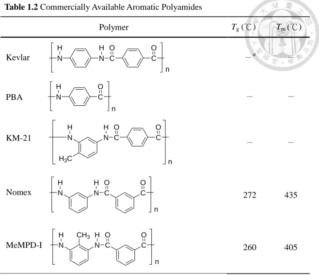
The properties of aromatic polyamides (aramids) are different from those of the aliphatic polyamides (nylons), e.g., heat resistance and low flammability. In general, they have high melting points above 300 ℃ and in many cases above 350 ℃. Some of the commercially available aromatic polyamides are listed in Table 1.2. The most widely known are Nomex and Kevlar aramid fibers, developed and commercialized by DuPont. The former is noted for its high thermal stability and typically used to make fire protective textile, and the latter is used as the high modulus and high strength fiber for bulletproof vests, radial tires, ropes, thermal insulating clothings, and advanced composites. Nomex aramid was introduced and commercialized by DuPont in 1961 as first commercial high-temperature synthetic fiber. It is based on poly(m-phenyleneisophthalamide), which contains meta-oriented chain segments of the AA-BB configuration. Kevlar aramid was introduced and commercialized by DuPont in 1972. It is based on poly(p-phenyleneterephthalamide), one of the para-oriented aromatic polyamides synthesized by S.L. Kwolek (a DuPont research scientist). Kevlar aramid can be prepared in a number of synthesis routes. The classical synthesis involves the low temperature polycondensation of p-phenylene diamine and terephthaloyl chloride in an amide solvent such as N-methyl-2-pyrrolidone (NMP) in the presence of metal salts like lithium chloride.
Kevlar aramid, like most para-oriented aromatic polyamides, is insoluble in conventional solvents. It is only soluble in strong acids such as concentrated sulfuric acid. There are two common methods for preparing the aromatic polyamide shown as the following.
1.1.1-1 High-temperature solution method
In 1971, Ogata11 reported an elegant synthesis of aromatic polyamides by the direct polycondensation of aromatic diamines with aromatic dicarboxylic acids in the
presence of an aryl phosphite and an organic base. In the original version of this novel synthesis for the preparation of polyamides, first reported by Ogata and referred to as a phosphorylation reaction,12 rather low-molecular-weight polymer was produced.
Two significant modifications, presented by Yamazaki, were developed by using triphenyl phosphite (TPP) and pyridine as condensing agents13 and addition of LiCl to the solvent14 for the reaction and led to a considerable increase in the molecular weight of the polymers produced (as shown in Scheme 1.1). Since that time, many attempts have been made to modify the reaction conditions in order to increase the molecular weight of polyamides. For example, Preston and Hofferbert15 reported that the reaction temperature was raised from 80 to 100 ℃, and this higher temperature was subsequently adopted for the synthesis of a variety of polyamides. In 1982, Higashi et al.16 showed that poly(p-phenylene terephthalamide) (Kevlar) with inherent viscosity of 4.5 dL/g could be obtained by using a solvent medium containing both LiCl and CaCl2. Krigbaum and coworkers17-19 have referred to these as Higashi conditions in a series of studies, and they advocated20, 21 increasing the reaction temperature from 100 to 115 ℃ for the synthesis of Kevlar using Higashi conditions to obtain an inherent viscosity of 6.2 dL/g. The direct polycondensation is the most popular and convenient method for preparing aromatic polyamides due to its high efficiency in the attainment of high-molecular-weight polymers.
Scheme 1.1 Direct polycondensation
Table 1.2 Commercially Available Aromatic Polyamides
Polymer Tg (℃) Tm (℃)
N N C C
Kevlar
H O
H O
n
-a -
N C
O H
PBA
n
- -
N H3C
N C C
H O O
H
n
KM-21 - -
N N C C
Nomex
H
H O O
n
272 435
N N C C
MeMPD-I
H
H O O
n CH3
260 405
a Not detected.
1.1.1-2 Low-temperature solution method22
The low temperature solution method is generally preferred when the diacid chloride can be easily. For example, Kavlar was prepared in NMP by p-phenylenediamine (PPD) and terephthaloyl dichloride (TPC) with some solubility promoters (CaCl2) (as shown in Scheme 1.2). The major defect of this way is requested high monomer purity for the purpose of getting high molecular weight of polyamide.23
Scheme1.2
NH2
H2N C C C C
O O
Cl Cl
O O
N N
H H
n +
-2n HCl
1.1.2 Preparation of Aromatic Polyimides
Aromatic polyimides can be categorized as an important class of materials because of their many desirable characteristics and often replace glass and metals in many industrial applications, especially in the semiconductor and electric packaging industry. The outstanding properties of aromatic polyimides come from their rigid backbones and strong intramolecular and intermolecular forces between the polymer chains due to the charge transfer complex formation between electron-donating (diamine moiety) and electron-accepting (dianhydride moiety) segments. Some of the commercially available aromatic polyimides are listed in Table 1.3. In 1956, Endrey took on his DuPont research assignment to seek an aromatic polyimide film prepared via a soluble intermediate polymeric precursor. He evaluated several solvents that dimethyl formamide (DMF) was an excellent solvent and successful synthesized the first poly(amic acid) film and demonstrated thermal conversion to polyimide film based on oxydianiline-pyromellitic dianhydride (ODA-PMDA). In 1965, the first aromatic polyimide line began production of film, designated as Kapton, with almost immediate success. Kapton is used in a wide variety of applications such as substrate for flexible printed circuit and insulation for transformer and capacitor. In addition, other significant aromatic polyimides have been prepared such as the Upilex series of polyimides derived from biphenyl dianhydride (BPDA) invented by Ube industries.
LARC-TPI is a thermoplastic polyimide developed by NASA Langley Research Center, primarily as a high temperature adhesive. Occidental Chemical Co. pioneered the synthesis of oxydiphthalic dianhydride (ODPA) and defined the properties of ODPA-based polyimides. Aromatic polyimides can be prepared from a variety of starting materials, by a variety of synthetic routes. One of the some synthetic methods is shown as the following. Polymerization of diamines and dianhydrides in the classic two-stage method of polyimides synthesis, an aromatic tetracarboxylic dianhydride is
added to a solution of aromatic diamine in a polar aprotic solvent. The generated soluble poly(amic acid) can be fabricated into shaped products, and then cyclodehydrated to the corresponding polyimide by extended heating at elevated temperatures (thermal imidization) or by treatment with chemical dehydrating agents (chemical imidization) (as shown in Scheme 1.3).24-27 In addition, a simple one-step preparation of soluble polyimides with high molecular weight was accomplished by heating to 200 ℃ in m-cresol.28
Scheme 1.3 Two-stage method of polyimides synthesis
O Ar' O Ar NH2
H2N
O
O O
O
N C H O
HOOC
COOH C N O H Ar'
n
N Ar' N O
O O
O
Ar n
Ar
Table 1.3 Commercially Available Aromatic Polyimidesa
Polymer Tg (℃) Tm (℃)
N N O
O
O
O
O n
Kapton 399 -b
C O N N
O
O
O
O
C O
n
LARC-TPI 264 -
C O N N
O
O
O
O
S O O
n
PIS 273 -
N O
O
O C
CH3 CH3
O N
O
O n
Ultem 217 -
a Ref. 5and 7. b Not detected.
1.1.3 Modification of Aromatic Polyamides and Polyimides
Aromatic polyamides and polyimides are generally limited by limited solubility in most organic solvents and their high glass transition (Tg) or melting temperatures caused by the high crystallinity and high stiffness of the polymer backbones, and strong intermolecular interaction through hydrogen bonding (in polyamides) and charge transfer complex formation (in polyimides). Thus, they are generally difficult to be cast into articles and their applications are restricted in many fields. Processable engineering plastics possessing moderately high softening temperatures and/or solubility in most organic solvents are required for practical use. For this reason,
much effort has focused on the synthesis of soluble and/or thermoplastic polyamides and polyimides without sacrificing their desired thermal and mechanical properties.
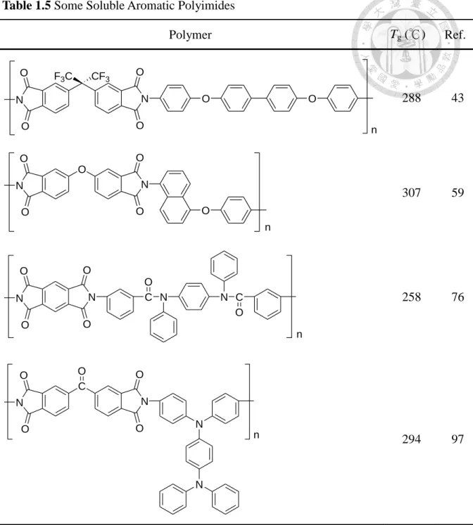
Several successful approaches of the chemical structure modification have been employed to improve the solubility and processability of these polymers. One of these approaches is the introduction of polar and flexible or kinked groups such as aryl ether (-O-), ketone (-CO-), ester (-COO-), methylene (-CH2-), isopropylidene [-C(CH3)2-], hexafluoroisopropylidene [-C(CF3)2-], sulfide (-S-), and sulfone (-SO2-) etc. into the polymer chains.29-45 It has been generally recognized that one or more flexible linkages inserted in aromatic main chains not only create bent bonds in the polymer chain, but also permit the rotation of aromatic units with a lower energy of internal rotation. In general, such a structural modification leads to a lower glass transition temperature and significant improvement in solubility. Another approach consists in the replacement of symmetrical aromatic rings by the asymmetrical ones, which leads to a decrease in packing efficiency and crystallinity.46-59 In addition, the introduction of bulky pendant substituents along the polymer skeleton60-87 and kinked or non-coplanar structures88-97 into the rigid polymer backbones can also be employed to decrease the order along the chain, enhance solubility, and disrupt crystallinity and intermolecular interaction due to a random arrangement of substituents. Even incorporation of bulky, three dimensional propeller-shaped TPA that in increased chain-packing distances and decreased intermolecular interactions units along the polymer backbone. All the polymers were amorphous with high Tg and enhanced thermal stability, showed good solubility in many aprotic solvents, and good film-forming capability. These modifications have lowered the melting temperatures and led to soluble and amorphous polymers (Table 1.4 and 1.5). In general, amorphous polymers have a lower softening temperature (Ts) and improved solubility as compared with their crystalline analogues.
Table 1.4 Some Soluble Aromatic Polyamides
Polymer Tg (℃ ) Ref.
204 33
239 36
264 51
206 80
276 96
N N C O C
H CH3
CH3
O C
O H O
n
N N C O S O C
O O
O O
H H
O N
N C H O
C H
O n
O O N
N H
C C
O O
H
n
N
N
N
N C H O
C O H
n
Table 1.5 Some Soluble Aromatic Polyimides
Polymer Tg (℃) Ref.
288 43
307 59
N N C
O
N N C
O O
O
O
O
n
258 76
C O N N
O
O O
O N
N
n 294 97
N N O
O
O
O
O O
n F3C CF3
O N N
O O
O
O
O
n
1.2 ELECTROCHROMISM98
When material gets the colour changing between a transparent state and a color state, or between two color states by receiving the electrical potentials, we may say it has electrochromic phenomenon or electrochromism.
Electrochromism is a phenomenon that occurs in certain materials. Those materials will undergo a reversible colour change if a specific electric potential is applied to them. These materials are referred to as electrochromic if the shifting of their redox states generates new or different visible region bands.99-104 This phenomenon was first termed electrochromism by Platt105 whose discussions were amongst the first publish in 1961. He indicated a colour generated via a molecular Stark effect in which orbital energies are shifted by an electric field. His work follows earlier studies by Franz106 and Keldysh107 in 1958, who applied huge electric fields to a film of solid oxide causing spectral bands to shift. In addition, the historical development of electrochromism is discussed by the Byker in 1994.108 Today, there are quite a variety of types of electrochromic material is developed. A typical representative of the electrochromic material is tungsten trioxide (WO3). Tungsten trioxide, with all tungsten sites as oxidation state WVI, is transparent as a thin film. On electrochemical reduction, WV sites are generated to give the electrochromic effect.109 Even though there is still controversy about the detailed coloration mechanism, it is generally accepted that the injection and extraction of electrons and metal cations (Li+, H+….) play a key role. In the case of Li+ cation, the reaction can be written (as shown in Scheme 1.4).
Scheme 1.4
With the discovery of this phenomenon has more than half a century, the application of electrochromic devices have mushroomed rapidly. Overall, electrochromic materials have the characteristics of high transmittance, low driving voltage and bistable advantages. This particular technology has great prospect and opportunities in the display industry and green energy market (as shown in Figure 1.1).
In energy saving market, the products such as smart windows and anti-glare car rearview mirrors have already been commercialized (as shown in Figure 1.2 and 1.3).98, 101, 110-113
One of the most famous examples is the EC window of Boeing 787.
Since 2008, Boeing 787 cabin window out of the traditional mechanical visor, using the smart windows with electrochromic technology. In the display industry, now more applications are in e-papers and electronic tag. But in the future, large advertising billboards and vehicle head-up display is very development of the market.
Whilst many types of chemical species exhibit electrochromism, only those with favourable electrochromic performance parameters98 are potentially useful in commercial applications. Thus most applications require electrochromic materials with a high contrast ratio, colouration efficiency (absorbance change/charge injected per unit area), cycle life, and write-erase efficiency (% of originally formed colouration that may be subsequently electro-bleached). Whereas displays need fast response times, by contrast „smart windows‟ can tolerate response times of up to several minutes. Generally the advantages of polymeric electrochromic materials that applied in electrochromic display can be summarized as following:
(1) Low driving voltage (< 1.5 or 3.5 V)
(2) Rapid response time [second (mirror)~ minute (window)]
(3) High color contrast (transmittance attenuation=ΔT> 30% ) (4) Long cycle life (window: >10 year, mirror: >3year)
(5) Environmental stability (electrochemical, thermal, & UV)
(6) Low cost, easy processing
(7) Multiple colors with the same material
Figure 1.1 Electrochromic products application categories.
Figure 1.2 Photographs of (a) smart windows (b) anti-glare back mirrors (c) and E-papers.112, 114
Figure 1.3 Switching sequence of the electrochromic glass.111
1.2.1 Electrochromic Systems
Up to now, a wide variety of EC materials have been developed, which can be classified into five distinct categories, namely, transition-metal oxides (especially tungsten oxide); inorganic coordination complexes (Prussian blue and phthalocyanines);115 organic molecules (4,4‟-bipyridylium salts and quinone, in solution and as polymer films); conjugated polymers (side-chain-substituted polymers or main-chain fully conjugated polymers);98, 99, 116
and arylamine-based polymers (polyimide types, polyamide types and epoxy types).117-119 Five different categories mentioned above have been developed for the electrochromic materials shown as following.
1.2.1-1 Transition-metal Oxides Tungsten Trioxide (WO3)
Many transition metal oxide films can be electrochemically switched to a non-stoichiometric redox state which has an intense electronic absorption band due to optical intervalence charge transfer.98, 100 A typical and most widely studied example is the tungsten trioxide (WO3) system, since its electrochromism was first reported in 1969.109 Tungsten oxide has a nearly cubic structure which may be simply described as an “empty-perovskite” type formed by WO6 octahedra that share corners. The empty space inside the cubes is considerable and this provides the availability of a large number of interstitial sites where the guest ions can be inserted. Tungsten trioxide, with all tungsten sites as oxidation state WVI, is a transparent thin film. On electrochemical reduction, WV sites are generated to give the electrochromic (blue coloration to the film) effect. Although, there is still controversy about the detailed coloration mechanism, it is generally accepted that the injection and extraction of electrons and metal cations (Li+, H+, etc.) play an important role. WO3 is a cathodically ion insertion material. The blue coloration in the
thin film of WO3 can be erased by the electrochemical oxidation. In the case of Li+ cations the electrochemical reaction can be written as Scheme 1.5.
Scheme 1.5 Iridium Oxide (IrO2)
In the case of tungsten trioxide, the more intensely absorbing redox state is produced on reduction (cathodic ion-insertion). In contrast, Group VIII metal oxides become coloured on electrochemical oxidation (anodic ion-insertion); as in the case of hydrated iridium oxide (strictly iridium hydroxide). The mechanism of colouration is uncertain, with both proton extraction and anion insertion routes being proposed. The first is based on cation loss (as shown in Scheme 1.6),120, 121 while the second is based on anion insertion (as shown Scheme in 1.7).122 Irrespective of whether the mechanism is hydroxyl insertion or proton extraction, Ir(OH)3 is the bleached form of the oxide and the coloured form is IrO2.123-126
Scheme 1.6
Scheme 1.7
1.2.1-2 Inorganic Coordination Complexes Prussian blue (PB)102
Prussian blue-PB ; ferric ferrocyanide, or iron (III) hexacyanoferrate (II) –first WO3 X(Li+ e-) LixWVI(1-X)WvxO3
(transparent) (blue)
Ir(OH)
3(colourless)
IrO
2H
2O H
+e
-(blue/grey)
Ir(OH)
3(colourless)
IrO
2H
2O H
2O e
-OH
-(blue/grey)
made by Diesbach in Berlin in 1704,127 is extensive used as pigment in the formulation of paints, lacquers and printing inks. Since 1978, Neff first reported the electrochromic properties Prussian blue [PB, iron(III) hexacyanoferrate(II)].126 PB becomes a famous electrochromism now because of its multiple changes in color, general formulation of PB is M‟k[M”(CN)6]l (M‟ and M” are transition metals with different oxidation number).115, 128 When the PB went through an electrochemical reduction process, the color could be changed from blue to colorless (as shown in Scheme 1.8). Moreover, due to an oxidation, the color of PB would be changed into yellow (as shown in Scheme 1.9).129
Scheme 1.8
[FeIIIFeII(CN)6] + e [FeIIFeII(CN)6] 2-
blue yellow
Scheme 1.9 Phthalocyanines102
Phthalocyanines (Scheme 1.10), similar to the electroactive system of Prussian blue, are tetraazatetrabenzo derivatives of porphyrins with highly delocalized p electron systems. Metallophthalocyanines are important industrial pigments used primarily in inks and for colouring plastics and metal surfaces. Since the first report of the polyelectrochromism of thin films of lutetium bis(phthalocyanine) Lu(Pc)2 in 1970, numerous metal phthalocyanines have been investigated for their electrochromic properties. Mechanical problems, such as film fracture and/or loss of adhesion to the electrode substrate, arise from anion ingress/egress during color switching. Despite such difficulties, Lu(Pc)2-based electrochromic displays with good reversibility, fast
[FeIIIFeII(CN)6] [FeIIIFeIII(CN)6] + e
blue colorless
response times, and little degradation over > 5 × 10⁶ cycles have been described.130
Scheme 1.10 Metallophthalocyanine (Pc) 1.2.1-3 Organic Molecules
Viologens131
The viologen (Scheme 1.11) are diquaternary derivatives of 4,4‟-biohenyl. The name comes from the fact that this class of compounds is easily reduced to the radical monocation, which is intensely blue colored. Of the three common viologen redox states (Scheme 1.11), the dication is the most stable and is colorless. When the dication gets an electron and the color will switch to blue or yellow. In addition, as the substituted group changes, such as increasing of the carbon chain length or conjugated growth, it will also change its color (Table 1.1).132-134 Viologens are investigated for use on EC systems because of their ability to change color reversibly many times upon reduction and oxidation.
Scheme 1.11 N
M N
N N
N N
N N
Phthalocyanine (Pc)
Table 1.6 Color of viologens based on different substituted structure135
-R Group Number of Effective Carbon
Color of First Reduction State
Methyl 1 blue
Ethyl 2 blue
Propyl 3 blue
Butyl 4 blue
Pentyl 5 purple
Hexyl 6 purple
Heptyl 7 mauve
Octyl 8 crimson
Iso-pentyl 4 purple
Benzyl 4-5 mauve
Quinones131
Many quinones are soluble, stable and only moderately coloured as neutral molecules, but on one-electron reduction, form brightly-coloured stable solid films of radical anion on the electrode.136-141
Benzoquinones (both ortho an para), 1,4-naphthoquinones, and 9,10-anthraquinones have been studied (Scheme 1.12), for example, 1 4-benzoquinone in propylene carbonate containing LiClO4.138 Coloured films were formed on cathode electrodes. Table 1.7 lists the electrochromic behaviors for electrochromic quinone-based systems.
In general, ortho benzoquinones are more electrochemically stable than their parar isomers, o-chloranil (3,4,5,6-tetrachorobenzoquinone) being the most stable quinone
studied, having a cycle life in excess of 105 cycles. Aminoanthraquinones show a more complicated electrochemical behavior than naphthaquinone: at moderate potentials, two redox couples are exhibited during cyclic voltammetry, representing first state followed at more negative potentials by a second reduction reaction (Scheme 1.13).
Scheme 1.12 Table 1.7 Color of quinone systems136-141
Quinone (RQ) Soild Film? Color of First Reduction State o-3,4,5,6-tetrachlorobenzoQ yes intense blue
o-3,4,5,6-tetrabromobenzoQ yes blue
p-benzoQ yes light blue
p-2,3,5,6-tetrafluorobenzoQ no yellow
p-2,3,5,6-tetrachlorobenzoQ no yellow
p-2,3-dicyano-5,6-dichlorobenzoQ no pink
5-aminonaphthoQ yes purple/blue
1-aminoanthraQ yes -
2-aminoanthraQ yes -
1,5-diaminoanthraQ yes purple
Scheme 1.13
1.2.1-4 Conducting Polymers
Widespread interest in conducting polymer is led to the award of the 2000 Nobel Prize in Chemistry to Shirakawa, Heeger and MacDiarmid.142
Types of electroactive conducting polymers including polypyrroles, polyanilines, and polythiophenes, poly(ethylenedioxythiophene) (PEDOT), poly(propylenedioxythiophene) (PProDOT), and poly(propylenedioxypyrrole) (PProDOP) (as shown in Scheme 1.14), are latently electrochromic in thin-film form, redox switching giving rise to new optical absorption bands in accompaniment with transfer of electrons and counter anions (as shown in Figure 1.4). In their oxidized forms, conducting polymers are charge balanced, doped with counter anions (p-doping) and have a delocalized π-electron band structure, oxidative p-doping shifts the optical absorption band towards the lower energy part of the spectrum. The color change or contrast between doped and undoped forms of the polymer depends on the magnitude of the bandgap of the undoped polymer.
Among the organic electrochromic materials, conducting polymers have received more attention because of their additional advantages over inorganic compounds.
Advantages and disadvantages of conducting polymers can be summarized as following (Table 1.8):
Scheme 1.14 Some conducting polymers.
Table 1.8 The advantages and drawbacks of conducting polymer143-145
Advantages Disadvantages
1. Outstanding coloration efficiency 1. Difficult to find a compatible counter electrode
2. Multiple color possibilities 2. Cycle life may be an issue 3. Easy to process, low cost 3. Environmental instability 4. Low driving voltage in devices
(< 1.5 or 0 V)
5. Rapid response time in device (~1 s)
S O O
R2 R1
n
S R1
n Polythiophene
Poly(propylenedioxythiophene) (PProDOT)
S n
O O
Poly(ethylenedioxythiophene) (PEDOT)
N H
n Polyaniline
N R
n Polypyrrole
R2
Poly(propylenedioxypyrrole) (PProDOP)
N O O
R2 R1
n R3
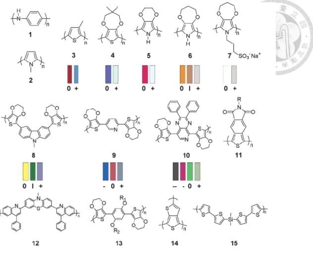
Figure 1.4 Representative electrochromic polymers. Color swatches are representations of thin films based on measured CIE 1931 Yxy color coordinates.
Key: 0 = neutral; I = intermediate; + = oxidized; − and − − = reduced.146
1.2.1-5 Arylamine-based Polymers
Aromatic amines (arylamines) are generally colorless unless they undergo some form of charge-transfer interaction with an electron-deficient acceptor species. By contrast, the product of one-electron oxidation yields a radical cation which, in organic solution, processes a brilliant color. Arylamines are thus candidate electrochromic materials.
Electron-rich triarylamines can be easily oxidized to form stable radical cations, and the oxidation process is always associated with a noticeable change of coloration.
Thus, studies of the synthesis and electrochromism of triarylamine-based polymers have been reported in the literature.147-149
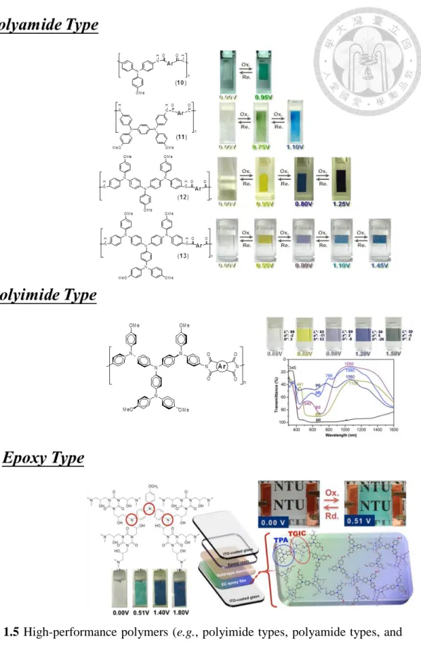
Notably, since 2005 our group has reported some solution-processable high-performance polymers (e.g., polyimide types, polyamide types, and epoxy types) utilizing the triarylamine units as an electrochromic functional moiety (Figure1.5),96,
97, 117-119
which showed interesting color transitions with good electrochromic reversibility in the visible region or near-infrared (NIR) range, and can be differentiated on the basis of method of increasing coloring stages. And the most significant advantage is that they all exhibit transparency at the natural state.
Figure 1.5 High-performance polymers (e.g., polyimide types, polyamide types, and epoxy types) utilizing the triarylamine units as an electrochromic functional moiety.
1.2.2 The Structure of Electrochromic Device
For electrochromic device (ECD) investigations a simple two-electrode system is constructed in a sandwich configuration (as shown in Figure 1.6).102 Generally, the ECD could be divided into four main parts including external electrical source, transparent conducting electrode, EC material layer, electrolyte layer, and ion-storage layer. The laminated ECD is easy to construct but rarely prepared due to the tendency of dissolved EC layer and leakage of liquid electrolytes. The brief descriptions of each layer are listed as following.
1.2.2-1 Transparent conducting layer
Transparent electrodes used on the both side of ECD not only transfer the electron into EC layer, but also provide a supporting substrate. The most important issue is the electrode needed to be transparent in visible region. Prior to these requirements, the transparent conducting oxide (TCO) such as indium-doped tin oxide (ITO), and fluorine-doped tin dioxide (FTO) deposited on glass or flexible substrate are adopted.
Among of these TCO materials, ITO is the best candidate due to low sheet resistance and high optical transmittance.
1.2.2-2 Electrochromic layer
EC layer is the most active layer in ECD which colored and bleached during charge transferring. The EC layer was deposited on one side of transparent conductor.
Thus, processability and coating method of EC layer are the crucial issues for preparing commercial products. Certainly, EC behavior such as response time and lifetime are important characteristic mentioned above.
1.2.2-3 Electrolyte layer
The electrolyte layer containing free ions is served as an electrically conductive medium. Therefore, electrolyte layer must be a good conductor for small voltages, and a good insulator for open-circuit condition. Furthermore, electrolyte layer also
need to be optical transparent. Electrochromic devices can be categorized in two types depending on the type of electrolyte (gel type and solid type). Although liquid type electrolyte provides faster responsibility of ECD, leaking of solution is a critical issue has to be solved. The electrolyte layer gives electrical contact and pathway for the ions to be injected into or ejected from the EC layer. Thus, the molecule size of ions affects the passing speed between EC layers. Generally, protons (H+), lithium (Li+), sodium (Na+), and potassium (K+) are used for this purpose.
1.2.2-4 Ion-storage layer
The counter electrode or an ion-storage layer of ECD is required to supply ions and provide colorless or a complementary color to the electrochromic layer. Thus, when the primary electrochromic film becomes dark due to the ion-intercalation, the ion-storage film should darken upon de-intercalation of ions. For example, NiO is a typical example of an ion-storage layer with WO3 thin film as an electrochromic layer.
+ + + + + + + + +
+ + +
+ + + +
+ + + +
M+
- - -
- - - -
- -
+ -
Figure 1.6 The schematic of typical ECD structure.
1.2.3 High Contrast Electrochromic Devices
On electrochromic applications, they are often used in shading or color change system. Most of the material is not to emphasize the contrast, but often in the pursuit of change in a variety of colors. In recent years, the pursuit of transparent-to-black electrochromic materials has become preeminent among various research trends in applied electrochromism. Intensive research is being carried out in this area and a number of systems exhibiting high contrast electrochromism have been reported to date. Following, we will discuss these studies have claimed that they are
„„transmissive-to-black‟‟.
This adjective was first termed by Reynolds et al. whose discussions were amongst the first publishes in 2008. But they were not claiming that their research is transmissive-to-black,150 but black-to-transmissive. Their approach towards making easily oxidized conjugated polymers with broad and homogeneous absorption bandwidths extending over the entire visible spectrum that can be fully bleached at the oxidation state. This device has a very high contrast ratio, ΔL * value of up to 53 (19 → 72). The next few years, most of the studies are based on conductive polymers.151-153 Since the conductive polymer having a long conjugated system, so most of the time in the natural state have very dark color. They can achieve a variety of color by increasing of conjugated length or changing of substituent groups.
Although this type of materials has a particularly excellent performance in the electrochromic system, but they are difficult to achieve of transmissive-to-black.
Until 2011, our group team published a kind of polyamide constituted by the aromatic amines.154 This material has a multi-color, and show a high degree of contrast (ΔL * = 50). The most significant feature of this type of electrochromic polymers based on aromatic amine is that they have a high degree of transparency in the natural state. This feature allows them to become the first to achieve
transmissive-to-black materials.
In the next few years, more and more studies published electrochromic material with high contrast.134, 155-168
Most of the material is focused on conducting polymers, only a small part of the study investigate in the small molecules, metallo-supramolecular polymers or conjugated polymers, their performance are summarized in Table 1.9.
High-contrast electrochromic materials on the market are very competitive. They can be applied in such anti-glare mirrors, smart windows or e-books. Characteristics of high contrast so that they can have good shading effect and higher resolution, so that greatly enhance the performance of the product.
Table 1.9 Publish papers. (Web of Science. Key word: „„electrochromic‟‟ and
„„transmissive-to-black‟‟)
Ref. Year L* at Natural State L* at Redox State ΔL*
150 2008 19 81 -62
151 2009 21 75 -54
152 2010 14 39 -25
153 2010 46 82 -36
154 2011 96 46 50
155 2011 32 83 -51
156 2011 52 85 -33
160 2012 60 83 -23
161 2013 76 22 54
166 2015 71 22 49
167 2015 88 32 56
168 2015 75 30 45
169 2016 56 1 55