國 立 交 通 大 學
電子工程學系電子研究所碩士班
碩 士 論 文
The study of optimal annealing process for ZrO
2gate
ISFETs in pH measurement applications
二氧化鋯作為閘極之離子感測場效電晶體應用在
pH 量測之最佳化退火製程研究
研 究 生: 詹秉燏
指導教授: 張國明 博士
桂正楣 博士
中華民國九十八年八月
二氧化鋯作為閘極之離子感測場效電晶體應用在
pH 量測之最佳化退火製程研究
The study of optimal annealing process for ZrO
2gate
ISFETs in pH measurement applications
研 究 生:詹秉燏 Student:Bin-Yu Chan
指導教授:張國明 博士 Advisor:Dr. Kow-Ming Chang
桂正楣 博士 Dr. Cheng-May Kwei
國 立 交 通 大 學
電子工程學系 電子研究所碩士班
碩 士 論 文
A Thesis
Submitted to Department of Electronics Engineering & Institute of Electronics College of Electrical Engineering and Computer Engineering
National Chiao Tung University In Partial Fulfillment of the Requirements
For the Degree of Master In Electronics Engineering August 2009 Hsinchu, Taiwan
中華民國九十八年八月
二氧化鋯作為閘極之離子感測場效電晶體應用在
pH 量測之最佳化退火製程研究
學生:詹秉燏 指導教授:張國明 博士
桂正楣 博士
國立交通大學
電子工程學系 電子研究所碩士班
摘 要
離子感測場效電晶體(Ion-Sensitive Field Effect Transistor, ISFET)首先是在 1970 年由 P. Bergveld 提出。其主要與傳統的 MOSFET 結構之差異,就是把金屬 閘極換成感測層以及將絕緣層暴露在電解液中。另外 ISFET 擁有許多優點,像 是成本低、尺寸小、輸出阻抗低、輸入阻抗高、響應時間快,因此非常適合應用 在生物感應器上。 我們在研究 pH-ISFET 的應用上時靈敏度是一個重要關鍵的因素。除此之外 還有限制了 pH-ISFET 應用的重要因素遲滯和漂移。為了得到高的靈敏度和低的 漂移以及遲滯,許多的感測層材料像是 SiO2, Al2O3, Si3N4 和 Ta2O5都被提出來 研究。在本篇論文中我們選擇二氧化鋯當作感測層去研究不同的退火溫度對於 pH-ISFET 的影響。 在本篇研究中,我們藉由研究靈敏度、遲滯和漂移來找出二氧化鋯作為閘極 pH-ISFET 之最佳的退火溫度。從實驗的結果我們可以發現在 600℃的退火溫度
有最大的靈敏度 54.5 mV/pH 和最小的漂移速率 0.54 mV/h。另外在 600℃的退火 溫度下遲滯也最小。遲滯在迴圈 pH = 7-3-7-11-7 比迴圈在 pH = 7-11-7-3-7 小, 大小分別為 1.43 和 5.45 mV。我們也看到遲滯在酸的迴圈比在鹼的迴圈小造成了 不對稱的遲滯結果。 從高的靈敏度、小的遲滯和低的漂移速率結果,我們可以推斷出最佳的退火 溫度是在 600℃。因此以二氧化鋯作為閘極的 pH-ISFET 在 600℃退火條件下非 常適合應用在 pH 量測上。
The study of optimal annealing process for ZrO
2gate
ISFETs in pH measurement applications
Student: Bin-Yu Chan Advisor: Dr. Kow-Ming Chang
Dr. Cheng-May Kwei
Department of Electronics Engineering & Institute of Electronics
National Chiao Tung University
ABSTRACT
The ion-sensitive field effect transistor (ISFET) was first reported by P. Bergveld in 1970s. In comparison to a conventional MOSFET structure, the metal gate is replaced by the sensing layer and exposing the insulator to the electrolyte. There are many advantages for the ISFET, such as, low cost, small size, low output impedance, high input impedance, and rapid response. Therefore, it’s very suitable for the biosensor applications.
The sensitivity is a key factor for the application of pH-ISFETs. On the side, the hysteresis and drift are the most important factors that prohibit the application of the pH-ISFETs. In order to obtain high sensitivity, low drift and hysteresis, many pH-sensitive materials, such as, SiO2, Al2O3, Si3N4 and Ta2O5 have been investigated.
In this thesis, we choose ZrO2 as the sensing film and investigate the influences of
In this study, we find the optimal annealing temperature by investigating sensitivity, hysteresis and drift for ZrO2 gate pH-ISFET. Form the experimental
results, we can find that annealing temperature of 600℃ has a maximal sensitivity of 54.5 mV/pH and minimal drift rate of 0.54 mV/h. In addition, the annealing temperature of 600℃ also shows the smallest hysteresis. The hysteresis in pH loop 7-3-7-11-7 is smaller than that in pH loop 7-11-7-3-7, with the magnitude of 1.43 and 5.45 mV, respectively. We also observe that the hysteresis of the acid side is smaller than basic side, results in asymmetric hysteresis.
From the result of high pH-sensitivity, small hysteresis and low drift, we can conclude the optimal annealing temperature is around 600℃. It reveals that ZrO2 gate
誌 謝
在我碩士兩年的期間,我首先要感謝張國明及桂正楣老師對我的指導與教 誨,讓我能在實驗上和半導體元件與製程上的知識有許多的進步,並且能夠完成 這篇論文,另外張國明老師也教導了我許多做人處事的道理,對我以後在進入社 會工作時有莫大的幫助。 其次我要感謝王水進老師以及賴瓊惠老師在我口試的時候,對我這篇論文提 出的問題和建議,讓我的論文可以更加的完整。 此外,我要感謝張知天學長,給了我明確的方向,以及在實驗的過程中不斷 的給予建議和鼓勵,還有我同組的組員詹仲逸、林卓慶、詹昆謀實驗上的互相幫 助,以及實驗室同學育彬、堃濠和老古給予的幫助,還有學長庭嘉、詩帆、同學 汶錦、阿魁、學弟重顯、煒力、學威陪我度過歡樂的時光。另外我還要感謝我的 女朋友禕倩,在我低潮的時候給我鼓勵,讓我有信心繼續研究下去。 最後我要感謝我的家人,父親詹英修先生、母親徐鳳嬌女士以及姐姐詹韻儒 小姐,他們的支持和鼓勵,讓我可以無後顧之憂的準備我的課業,順利完成我的 碩士論文取得碩士學位。 誌于 2009.08 詹秉燏
Contents
Abstract
(in Chinese)
--- iAbstract
(in English)
--- iiiAcknowledgement
--- vContents
--- viFigure Captions
--- viiiTable Captions
--- xiChapter 1
Introduction
1.1 Introduce to ISFETs--- 11.2 The pH glass electrodes--- 2
1.3 The solid-state reference electrodes--- 3
1.4 Intrinsic properties of ISFETs--- 4
1.5 Motivation of this work--- 4
1.6 References--- 5
Chapter 2
Theory Description
2.1 The concept of pH--- 72.2 Theory of ISFET--- 7
2.2.1 Operation principle of ISFET--- 8
2.2.2 The oxide-electrolyte interface--- 10
2.3 Hysteresis--- 13
2.4 Drift--- 13
2.4.1 Dispersive Transport--- 14
2.4.2 Expression for Drift--- 15
2.5 Reference--- 17
Chapter 3
Experiment and Measurement
3.1 ISFET fabrication Process flow--- 203.2 Experiment details--- 21
3.2.1 Gate region formation--- 21
3.3 Measurement system--- 22
3.3.1 Preparation before measuring--- 22
3.3.2 Setup of the I-V measuring system--- 23
3.3.3 Setup of hysteresis measuring system--- 24
3.3.4 Setup of drift measuring system--- 24
3.4 References--- 24
Chapter 4
Results and Discussions
4.1 Introduction--- 264.2 pH sensitivity--- 26
4.3 Hysteresis effect to pH-ISFET--- 27
4.4 Drift phenomenon to pH-ISFET--- 28
4.5 Conclusion--- 29
4.6 Reference--- 30
Figure captions
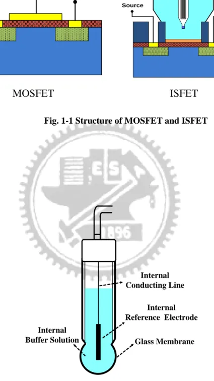
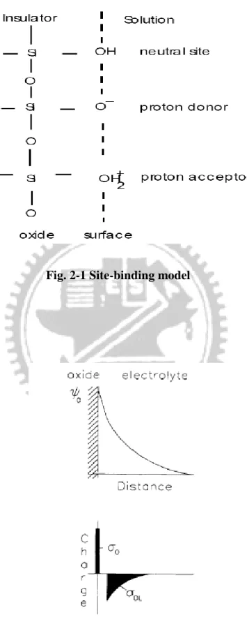
Figure 1-1 Structure of MOSFET and ISFET Figure 1-2 Conventional glass electrode Figure 2-1 Site-binding modelFigure 2-2 Potential profile and charge distribution at an oxide electrolyte solution interface
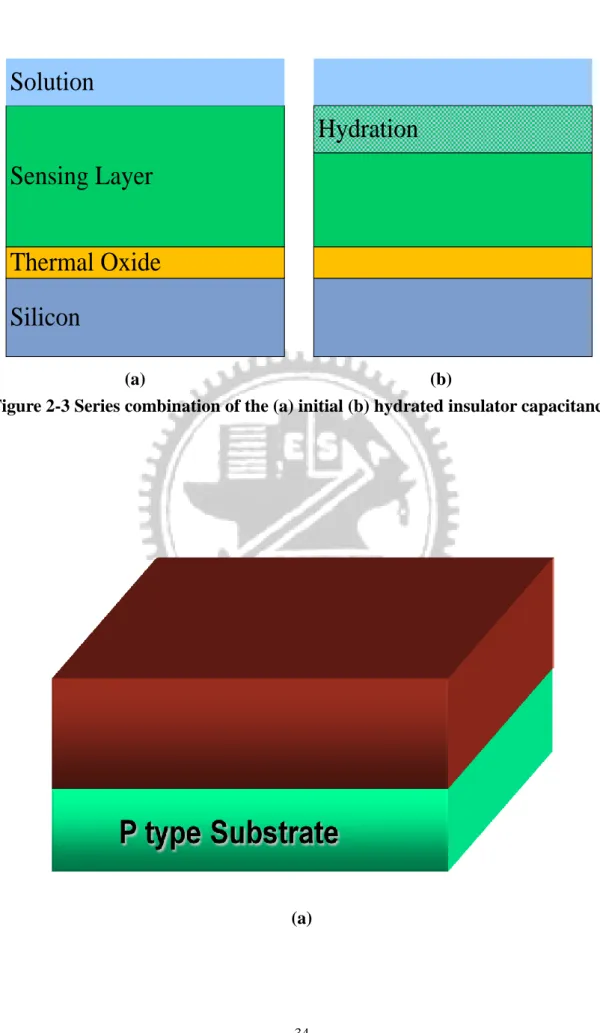
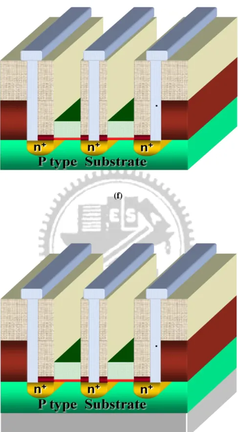
Figure 2-3 Series combination of the (a) initial (b) hydrated insulator capacitance Figure 3-1 Fabrication process flow
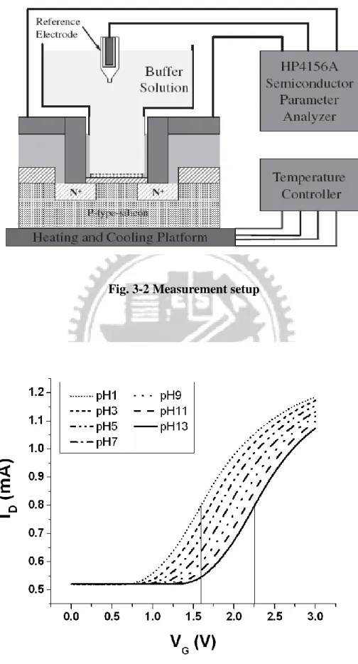
Figure 3-2 Measurement setup
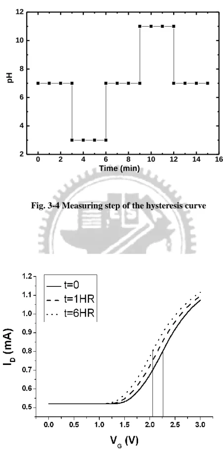
Figure 3-3 Extraction method of sensitivity Figure 3-4 Measuring step of the hysteresis curve Figure 3-5 Detection principle of drift
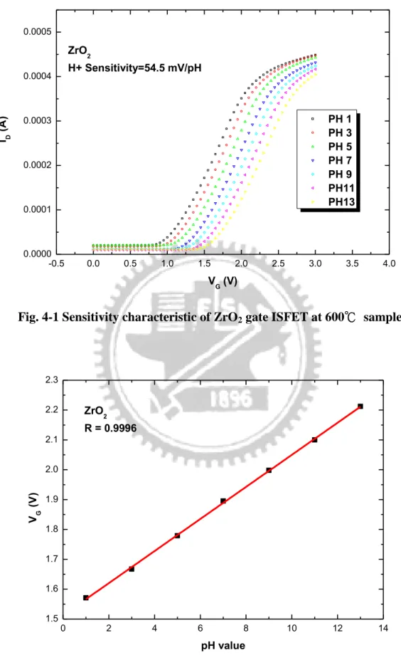
Figure 4-1 Sensitivity characteristic of ZrO2 gate ISFET at 600℃ sample
Figure 4-2 Linearity characteristic of ZrO2 gate ISFET at 600℃ sample
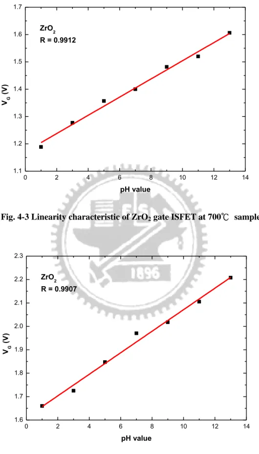
Figure 4-3 Linearity characteristic of ZrO2 gate ISFET at 700℃ sample
Figure 4-4 Linearity characteristic of ZrO2 gate ISFET at 800℃ sample
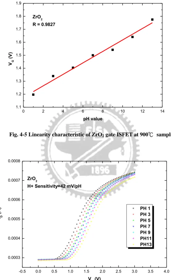
Figure 4-5 Linearity characteristic of ZrO2 gate ISFET at 900℃ sample
Figure 4-6 Sensitivity characteristic of ZrO2 gate ISFET at 700℃ sample
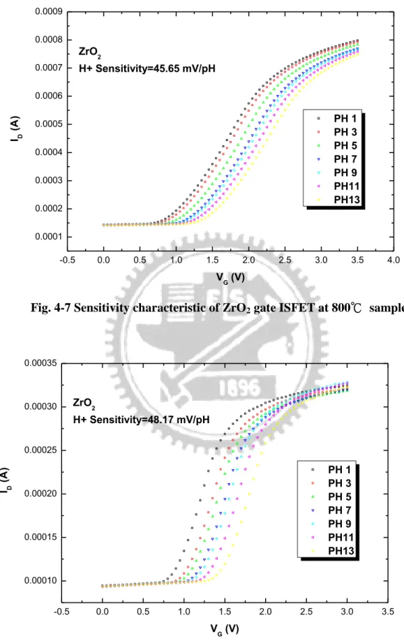
Figure 4-7 Sensitivity characteristic of ZrO2 gate ISFET at 800℃ sample
Figure 4-8 Sensitivity characteristic of ZrO2 gate ISFET at 900℃ sample
Figure 4-9 Sensitivity characteristic of ZrO2 gate ISFET at not annealed sample
Figure 4-10 Linearity characteristic of ZrO2 gate ISFET at not annealed sample
Figure 4-11 SEM image of ZrO2 gate ISFET at not annealed sample
Figure 4-12 SEM image of ZrO2 gate ISFET at 600℃ sample
Figure 4-14 SEM image of ZrO2 gate ISFET at 800℃ sample
Figure 4-15 SEM image of ZrO2 gate ISFET at 900℃ sample
Figure 4-16 The pH sensitivity of ZrO2 gate pH-ISFET annealed at different
temperature
Figure 4-17 Hysteresis curves of ZrO2 gate ISFET at pH loop 7-3-7-11-7 to 600℃
sample
Figure 4-18 Hysteresis curves of ZrO2 gate ISFET at pH loop 7-3-7-11-7 to 700℃
sample
Figure 4-19 Hysteresis curves of ZrO2 gate ISFET at pH loop 7-3-7-11-7 to 800℃
sample
Figure 4-20 Hysteresis curves of ZrO2 gate ISFET at pH loop 7-3-7-11-7 to 900℃
sample
Figure 4-21 Hysteresis curves of ZrO2 gate ISFET at pH loop 7-3-7-11-7 to not
annealed sample
Figure 4-22 Hysteresis curves of ZrO2 gate ISFET at pH loop 7-11-7-3-7 to 600℃
sample
Figure 4-23 Hysteresis curves of ZrO2 gate ISFET at pH loop 7-11-7-3-7 to 700℃
sample
Figure 4-24 Hysteresis curves of ZrO2 gate ISFET at pH loop 7-11-7-3-7 to 800℃
sample
Figure 4-25 Hysteresis curves of ZrO2 gate ISFET at pH loop 7-11-7-3-7 to 900℃
sample
Figure 4-26 Hysteresis curves of ZrO2 gate ISFET at pH loop 7-11-7-3-7 to not
annealed sample
Figure 4-27 Drift in pH 7 buffer solution of ZrO2 gate ISFET for 6 hours at 600℃
Figure 4-28 Drift in pH 7 buffer solution of ZrO2 gate ISFET for 6 hours at 700℃
sample
Figure 4-29 Drift in pH 7 buffer solution of ZrO2 gate ISFET for 6 hours at 800℃
sample
Figure 4-30 Drift in pH 7 buffer solution of ZrO2 gate ISFET for 6 hours at 900℃
sample
Figure 4-31 Drift in pH 7 buffer solution of ZrO2 gate ISFET for 6 hours at not
Table captions
Table 3-1 Parameters of sensing layers deposition with Sputter Table 3-2 The different annealing condition of ZrO2 gate ISFET
Table 4-1 The comparison of different test loop in hysteresis
Chapter 1
Introduction
1.1 Introduce to ISFETs
Since P. Bergveld was first reported the ion-sensitive field-effect transistor for neuropsychological measurements in 1970 [1], more than 600 papers appeared in these 30 years devoted on ISFETs and another 150 on related devices, such as EnzymeFETs (ENFETs), ImmunoFETs (IMFETs), etc [2]. The ISFET device is similar to the conventional MOSFET except that the metal gate is replaced by sensing layers, and the sensing layers are exposed to the buffer solution directly. The different between MOSFET and ISFET structure was shown in Fig. 1-1.
In the beginning, Bergveld and Sibbald describe the operational mechanism of the ISFETs with ID, as an expression for the drain current in the linear region. Hence, it
changes in the drain current are attributed to change in the electrostatic potential only. When the sensing layer immersed in the buffer solution, the electric potential between the electrolyte and the sensing layer is affected by the H+ concentration. This will bring about changing of the electric field at the insulator and semiconductor interface, and results different drain current.
In the past, different application of pH sensitive materials was found out because the characterization of SiO2 sensing layer is not ideal. For example, the property of
Si3N4 [3][4], SnO2 [5][6], Al2O3 [7], WO3 [8], Ta2O5 [9] and ZrO2 [10] sensing layer
are all better than SiO2 as a sensing layer. In addition, with the development of ISFET
of ion detecting device usually applies to medical respect.
To this day ISFET can utilize semiconductor manufacturing technology minimize component size and make different sensing membranes on the same chip. Therefore, it can detect many kinds of ion concentration with the small chip. The applications of this type of product are quite extensive, such as medicine, agriculture, environmental protection and chemical analysis, etc [11][12].
1.2 The pH glass electrodes
The first pH glass electrode is reported by Cremer in 1906 and after that many efforts have been devoted to improve its application. The glass electrode is composed of a bulb of glass membrane, which allows the passage of hydrogen ions, and a fixed concentration of HCl or a buffered chloride solution inside in contact with an internal reference electrode, which use of Ag/AgCl, as shown in Fig. 1-2.
When the glass electrode is immersed in the buffer solution, it can produce ion transfer in the interface between the bulb surface and the pH buffer solution. This reaction can build up hydrogen ions on the surface of ISFET [13] and makes the hydrogen ion exchanged stable in the solution. For the purpose of good and stable sensing glass, the sensing glass often contained other component like Na2O-CaO-SiO2,
Li2O-BaO-SiO2, Li2O-Cs2O-La2O3-SiO2, et al. [14]. For example, the introducing of
alkali (ex. Li) oxide will break the stable Si-O bond and result the change between Li+ and H+:
( _ ) ( )
SiO Li glass membrane H solution (1-1)
( _ ) ( )
SiO H hydrated layer Li solution
(1-2) The produced charges will transport by Li+, and build up surface potential. The
potential difference between the outside and inside glasses will be delivered to the pH meter and exhibit the potential difference in pH value. The potential difference across the glass membrane can be derived from Nernst equation:
ln H
RT E Eo
nF
(1-3) where E=electrode potential, Eo=standard potential of the electrode, R=gas constant
(8.31441JK-1mol-1), T=temperature (in Kelvin), n=valance (n=1 for hydrogen ions), F=Faraday constant and H=activity of hydrogen ions.
The glass electrode has ideal Nernstian response, stable and endurable; therefore, it is widely used for pH measurement. For the purpose of stable, the reference electrode materials must use the noble metal like Pt, Ag, et al, it is relatively expensive. Since the conventional glass electrode has to measure at vertical position for chemical stability, it prevents the applications in the measurement. In order to overcome these disadvantages, the all-solid-state pH glass electrode has been investigated [14] [15].
1.3 The solid-state reference electrodes
The materials of solid-state reference electrode normally use noble metal. And the property of noble metal material is steady; it is hard to react in the buffer solution.
Nevertheless it is unable to produce ion-exchange reactions like glass electrode. The solid-state reference electrode has the drawback of unstable voltage. It is because the
potential at the solid/liquid interface is thermodynamically undefined and will cause significant errors in pH measurement. The unstable problem may derive from the redox reaction or other reactions at noble metal reference electrode and the liquid
potential at the interface for the solid-state reference electrode integrated with ISFET.
1.4 Intrinsic properties of ISFETs
Even though the ISFET was reported over 39 years ago, the commercial products are developed very slowly. It is because the basic mechanisms, such as, temperature, light and time…etc. ISFET has two important time-dependent factors, drift and hysteresis. The drift suggests a temporal change in the threshold voltage of ISFET, which is not associated with surface response at the electrolyte and sensing layer interface. Therefore, the drift phenomenon could be described as the change in the insulator composition due to hydration of the surface. In addition, the hysteresis is affected by the slow response of the pH-ISFET. Both of drift and hysteresis will influence the output voltage accuracy and prevent the application of ISFET. For this reason, it is importance to reduce the drift and hysteresis impact on the pH-ISFET.
1.5 Motivation of this work
The pH-sensitivity is a key factor for the application of ISFETs. On the side, the hysteresis and drift are the most important factors that prohibit the application of the ISFETs. Therefore, in order to obtain high sensitivity, small hysteresis and low drift, we choose ZrO2 as the sensing layer and investigate the influences of different
annealing temperatures on the ZrO2 sensing film for the pH-ISFET.
According to the experiment results, we try to attain to the optimum annealing condition for ZrO2 as a pH-sensing layer.
1.6 References
[1] P. Bergveld, “Development of an ion sensitive solid-state device for neurophysiological measurements”, IEEE Trans.Biomed. Eng.,vol. BME-17, p.70, 1970.
[2] P. Bergveld, “Thirty years of ISFETOLOGY What happened in the past 30 years”. [3] H. K. Liao, J. C. Chou, W. Y. Chung, T. P., and S. K. Hsiung, ”Study on the
interface trap density of the Si
3N4/SiO2 gate ISFET” Proceeding of the Third East
Asian Conference on chemical Sensor, Seoul, South Korea, pp.394-400, November 1997.
[4] P. Woias, “Slow pH response effects of silicon nitride ISFET sensors”, Sensors and Actuators B 48, pp.501-504, 1998.
[5] Li-Lun Chi, “Study on extended gate field effect transistor with tin oxide sensing membrane”, Material Chemistry and Physics 63, pp19-23, 2000.
[6] Hung-Kwei Liao, “Study of amorphous tin oxide thin films for ISFET applications”, Sensors and Actuators B 50, pp.104-109, 1998.
[7] S. Jamasb, S. Collins, and R. L. Smith, “A physically-based model for drit in Al
2O3-gate pH ISFET’s”, Tech. Digest, 9 th
Int. Conf. Solid-State Sensors and Actuators (Transducers’97), Chicago, IL, 15-19, pp.1379-1382, June, 1997.
[8] Jung-Chuan Chou, “Ion sensitive field effect transistor with amorphous tungsten trioxide gate for pH sensing”, Sensors and Actuators B 62, pp.81-87, 2000.
[9] P. Gimmel, B. Gompf, D. Schmeiosser, H. D. Weimhofer, W. Gopel, and M. Klein, “Ta
2O5 gate of pH sensitive device comparative spectroscopic and electrical
studies”, Sensors and Actuators B vol. 17 pp. 195-202, 1989.
Zirconium Oxide Gate Ion-sensitive Field-Effect Transistors” Japanese Journal of Applied Physics Vol. 46 No.7A pp.4334-4338, 2007.
[11] Wang Zheng-Xiao, “Applications of penicillinase FET in penicillinfermentation engineering”, Sensors and Actuators B, 13-14 (1993) 568-569。
[12] Li-chan Zhong and Gao-xiang Li, “Biosensor based on ISFET for penicillin determination”, Sensors and Actuators B, 13-14 (1993) 570-571。
[13] Y. Q. Miao, J. R. Chen and K. M. Fang, “New technology for the detection of pH”, J. Biochem. Biophys. Methods, vol. 63, pp. 1-9, 2005.
[14] 董勝敏, 王承遇, 潘玉昆, ”pH 玻璃電極的現狀與發展”, GLASS & ENAMEL, vol. 32, No.2, pp.54-57, Feb., 2004.
[15] A.Noll, V. Rudolf, E. W. Grabner, ”A glass electrode with solid internal contact based on Prussian blue”, Electrochemica Acta, vol. 44, pp.415-419, 1998
Chapter 2
Theory Description
2.1 The concept of pH
pH is a measure of the acidity or basicity of a solution, it was first introduced by Danish chemist Søren Peder Lauritz Sørensen at the Carlsberg Laboratory in 1909. Aqueous solutions at 25℃ with a pH less than 7 are considered to be acidic. On the contrary, solutions with a pH greater than 7 are said to be basic. The name, pH, can be derived from a combination of “p” the word power “H” for the symbol of the element hydrogen [1]. The formula for calculating pH value is defined as:
(2-1) where is the activity coefficient and [H+] is the molar concentration of solvated protons in units of moles per liter. From Eq. (2-1), pH is defined as minus the decimal logarithm of the hydrogen ion activity in solution. The active term is used because pH reflects the amount of available hydrogen ions, not the concentration of hydrogen ions.
2.2 Theory of ISFET
The ion-sensitive field effect transistor (ISFET) was first reported by Bergveld in 1970[2]. In comparison to a conventional MOSFET, it is replaced by the sensing layer and exposing the insulator to the electrolyte. When the sensing layer exposed to the electrolyte, a change in the surface potential between the electrolyte and the sensing
10
log [ ]
pH H
layer will result from a change in the pH concentration in the electrolyte. This will cause an alteration in the electric field in conductance and current modulation. The followings are the theoretical foundations which are mostly adopted to characterize the ISFET.
2.2.1 Operation principle of pH-ISFET
Since ISFET sensors are based on field effect principles, the standard equations of MOSFET have been extended to ISFET and integrated with the pH variation terms. The general expression for drain current of MOSFET and thus also of ISFET in non-saturated region is [3]:
GS T
DS DS OX D V V V V L W C I 2 1 (2-2) where COX is the gate insulator capacitance per unit area; μ is the electron mobility inthe channel; W/L is the width-to-length ratio of the channel; VGS is gate to source
voltage; VDS is drain to source voltage and VT is the threshold voltage. VT can be
described by following expression:
F OX B FB T C Q V V 2 (2-3) where VFB is the flat-band voltage; QB is the depletion charge in the silicon substrate,
andψF is the potential difference between the Fermi level and intrinsic Fermi level.
The degree ofψF is dependent on the doped concentration. VFB can be described by
following expression: OX SS OX Si M FB C Q Q q V (2-4)
QOX is the charge in the oxide and QSS is the surface state density at the oxide-silicon
interface. Substitution of Eq. (2-3) in Eq. (2-4), the general form of the threshold voltage of a MOSFET can be described by following expression:
F OX B SS OX Si M T φ C Q Q Q q V 2 (2-5) Form Eq. (2-5) it can be seen that the threshold voltage of a MOSFET is determined by material properties such as the workfunction Φ and the charge accumulation. For a stable operation of a MOSFET it is importance that the threshold voltage is constant which can be achieved by applying an appropriate MOS process such as ion implantation. Eq. (2-2) shows that the drain current is now only a function of the gate voltage, using a constant drain-source voltage [4]
In the case of ISFET, two more differences has to be explained, the interfaces between the liquid and the sensing layer on the side, the liquid and reference electrode at the other side. The interface potential at the sensing layer and electrolyte interface is determined by surface dipole potential of the solution χsol, which is a constant, and the surface potential Ψ0 which results from a chemical reaction, usually controlled by
the dissociation of oxide surface group. And then the interface potential between the liquid and the reference electrode is the reference electrode potential relative to vacuum Eref. Hence the ISFET threshold voltage becomes the following equation:
F OX B SS OX Si sol ref T φ C Q Q Q q Ψ χ E V 0 2 (2-6) In Eq. (2-6), all terms are constant except Ψ0, it is the kernel of ISFET sensitivity
to the electrolyte pH which is controlling by the dissociation of the oxide surface. In order to obtain an accuracy pH value, to investigate a high pH sensitivity ISFET on the electrode-electrolyte interface is important, so in next section we will give more
discussions.
2.2.2 The oxide-electrolyte interface
The surface of any metal oxide always contains hydroxyl groups, in the case of silicon dioxide SiOH groups [5]. These groups consist of donate and accept a proton from the solution, and the mechanism responsible for the oxide surface charge can be described by the site-binding model as illustrated in Fig 2-1 [6], which describes the equilibrium between the so-called amphoteric SiOH surface site and theHS-ion in the solution. The reactions are:
2 a SiOH SiOH HS K (2-7) S -K H SiO SiOH b (2-8) where HS represents the protons at the surface of the oxide, Ka and Kb are the
chemical equilibrium constants, the equilibrium constants Ka and Kb are given by:
S 2 a ] ][ [ ] [ K H SiOH SiOH (2-9) ] [ ] ][ [ K S b SiOH H SiO- (2-10) where S means the surface.
The potential between insulator oxide and electrolyte solution causes a proton concentration different between the bulk and surface that based on Boltzmann:
kT q a a B S H H 0 exp Ψ (2-11) or kT q PH PHs B 3 . 2 0 Ψ (2-12)
Where aH the activity of H+; q is is the elementary charge; k is the Boltzmann constant
and T is the absolute temperature. The subscripts B and S refer to the bulk and the surface, respectively. We also have to know that there are a fixed number of surface sites per unit area, Ns:
(2-13) Base on some electrochemical knowledge and math derivation, we can obtain the surface charge density
(2-14) where B is the number of negatively charged groups minus the number of positively charged groups in mole per unit area. The combination of Eq. (2-9) to (2-14) yields:
(2-15)
where Ka and Kb are dissociation constant. A detailed derivation can see the Ref. [5].
After we get the surface charge density, we can find the intrinsic buffer capacity , the capability of the surface to store charge as result of a small change in the H+ concentration, defined as:
int 0 q PHs (2-16)
From Eq. (2-15) and (2-16)
(2-17)
It is called “intrinsic” buffer capacity, because it is only capable of buffering small changes in the surface pH (PHs) and not in the bulk pH (PHb). We can see that the
value of Ns, Ka and Kb are oxide dependent. More surface sites will obtain larger .
2 S AOH AOH AO N 2 [ / ] o C m
2
o q AOH AO qB 2 2 S S S a b H o a b b H H a K K qNs K K K a a int
2 2 int 2 2 4 2.3 S S S S S b H a b H a b S H a b b H H K a K K a K K N a K K K a a int Because of charge neutrality, an equal but opposite charge is built up in the electrolyte solution side of the double layer DL as shown in Fig. 2-2. This charge
can be described as a function of the integral double layer capacitance, Ci, and the
electrostatic potential: 0 0 DL Ci (2-18) The integral capacitance will be used later to calculate the total response of the ISFET on changes in pH. The ability oh the electrolyte solution to adjust the amount of stored charge as result of a small change in the electrostatic potential is the differential capacitance, Cdif:
dif DL C 0 0 0 Ψ Ψ (2-19) As a result, combination of Eq. (2-16) to (2-19) results in an expression for the sensitivity of the electrostatic potential change in
S H a : ) 3 . 2 ( C 0 0 int 0 0 0 0 kT q PH q PH PH B dif s s Ψ (2-20)
From Eq. (2-20), we get a general expression for the sensitivity of the electrostatic potential to changes in the bulk pH [5]:
q kT PHB 2.3 0 (2-21) with 1 3 . 2 1 int 2 q kTCdif (2-22)
the parameter α is a dimensionless sensitivity parameter that varies between 0 and 1, depending on the intrinsic buffer capacity, β int, of the oxide surface and the
must to be 1, so that the ISFET has a so-called Nernstian sensitivity of precisely [7]. It appears that the usual SiO2 from MOSFET does not fulfill the requirements of a
high value ofS. The pH sensitivity is only about 30mV/pH, so research nowadays is to find high sensitivity sensing film. Here we select ZrO2 as a sensing film, the higher
value of S which means Nerstian sensitivity can be achieved.
2.3 Hysteresis
There are many advantages for the ISFET, such as, low cost, small size, low output impedance, high input impedance, and rapid response [8], [9]. It’s very suitable for the biosensor applications. However, the hysteresis and drift are the nonideal factors that prevent the applications of the ISFET. Therefore, in order to extend the applications of the ISFET, it is important to measure these nonideal factors.
The hyseresis also called memory effect; it is affected by the slow response of the pH-ISFET. The amplitude of the slow response is quite small (3% to 7% of the total response) but will continue for several hours [10]. Because of the slow response is the response of reactive sites in the bulk, such as, buried sites, not like the fast response is related to the surface sites reaction [11] [12]. It results different output voltages when pH-ISET was measured many times at the same pH value. Because the ions diffuse to the buried sites for reaction, it will come into being a slow response. And this voltage deviation is defined as the hysteresis.
2.4 Drift
When ISEET immerses in the buffer solution for a long time, and the intrinsic response is completed. The output voltage of the pH-ISFET still varies with time gradually and monotonically. This phenomenon is called ”Drift”. According to Ref [13], it is difficult to identify the reason of this phenomenon, which could be either a surface or a bulk effect, or both. Some possible causes of drift have been proposed as following:
(1) Variation of the surface state density (Dit) at the Si/SiO2 interface which means the
drift dependence of diffusion mechanism.
(2) Drift of sodium ion under the influence of the insulator field. Given an effective diffusion coefficient Deff, it is clear that a bulk redistribution of sodium which has left
a trap near the edge of the SiO2.
(3) Some surface effects, such as the rehydration of a surface that is partially dehydrated and ion exchange involving OH- ions.
(4) Injection of electrons from the electrolyte at strong anodic polarizations created negative space charge inside sensitive films.
According to Ref [14], the drift rate of SnO2 gate pH-ISFET is increasing with
pH value. The existence of OH- ion is one of the factors that causes the drift .The OH- ions which exist in the acid solutions are lesser than in basic solution. For this reason, we can find out the drift rate increasing with pH value.
2.4.1 Dispersive Transport
Dispersive transport was brief reviewed in [15] and it is observed in a broad class of disordered materials. In an amorphous material, dispersive transport may arise from hopping motion through localized states (hopping transport), trap-limited transport in the presence of traps possessing an exponential energy distribution (multiple-trap transport), or a combination of the aforementioned transport mechanisms (trap-controlled hopping transport) [16]. Regardless of the specific dispersive mechanism involved, however, dispersive transport leads to a characteristic power-law time decay of diffusivity [17] which can be described by: [18]
1 0 00( ) ) (t D t D (2-23) where D00 is a temperature-dependent diffusion coefficient which obeys an Arrhenius
relationship, ω0 is the hopping attempt frequency, and β is the dispersion parameter
satisfying 0<β<1. Dispersive transport leads to decay in the density of sites/traps occupied by the species undergoing transport. This decay is described by the stretched-exponential time dependence given by
] ) / exp[( ) 0 ( ) ( / / t N t NS T S T (2-24) where ΔNS/T(t) is the area density (units of cm-2) of sites/traps occupied, τ is the time
constant associated with structural relaxation, and β is the dispersion parameter.
2.4.2 Expression for Drift
The drift phenomenon could be defined as a function of pH value [19]. The heavier OH- ions cause a larger drift rate. It is suggested that the decrease in the
shift of threshold voltage. The overall insulator capacitance can be determined by the series combination of the surface hydration layer and the sensing film, will exhibit a slow, temporal change. When drift phenomenon occurs at the surface of an actively-biased ISFET, the gate voltage will simultaneously exhibit a change to keep a constant drain current. The change in the gate voltage can be written as:
) 0 ( ) ( ) ( G G G t V t V V (2-25) Since the voltage drop inside of the semiconductor is kept constant, ΔVG (t) becomes
)] 0 ( ) ( [ )] 0 ( ) ( [ ) ( FB FB ins ins G t V t V V t V V (2-26) where VFB is the flatband voltage and Vins is the voltage drop across the insulator. VFB
and Vins are given by the following expression:
OX SS OX Si sol ref FB C Q Q q Ψ E V 0 (2-27) OX inv B ins C Q Q V ( ) (2-28) where Qinv is the inversion charge. If the temperature, pH, and the ionic strength of the
solution are held constant, Eref, χsol, Ψ0, and ΦSi can be neglected, so the drift can be
rewritten as: ) 0 ( 1 ) ( 1 ) ( ) ( I i inv B SS OX G C t C Q Q Q Q t V (2-29)
In this study, the gate oxide of the fabricated ISFET was composed of two layers, a lower layer of thermally-grown SiO2 of thickness, dL, and an upper layer of
sputter-grown ZrO2 of thickness, dU.. CI(0) is the effective insulator capacitance given
by the series combination of the thermally-grown SiO2 capacitance, εL/dL, and the
sputter-grown ZrO2 capacitance, εU/dU. Ci(t) is analogous to CI(0), but an additional
hydrated layer of capacitance make Ci always smaller than CI, εHL/dHL, at the
oxide-electrolyte interface must be considered. The sputter-grown ZrO2 capacitance is
Fig. 2-3. Hence, the drift is given by: ) ( ) ( ) (t Q Q Q Q d t V HL HL U HL U inv B SS OX G (2-30)
From this equation, we observed that drift of gate voltage ΔVG if the substrate type
was different; it might to be positive or negative value. Because of the value of ΔVG is
positive or negative, it is depend on the Qinv and QB . Other terms at Eq. (2-30) can be
appropriate as constant value no matter what the substrate is. According to this assume it is possible to eliminate the drift or hold the drift to be a constant at any other pH aqueous solution through the CMOS ISFET. By applying dispersive transport theory, an expression for dHL(t) is given by [15]
) / ( exp 1 ) ( ) (t d t dHL HL (2-31) with hydr D T S HL N A N D d ) 0 ( ) ( / 1 0 00 (2-32) where AD is the cross-sectional area, and Nhydr is the average density of the hydratingspecies per unit volume of hydration layer. Therefore, combination of Eq. (2-25) to (2-32) the gate voltage drift can be expressed by the following expression:
) / ( exp 1 ) ( ) ( ) (t Q Q Q Q d t V HL HL U HL U inv B SS OX G (2-33)From Eq. (2-33), we can expect that if the time of gate oxide immersing in the buffer solution is long enough (determined by the constant ), the gate voltage drift will approach a constant value which is greatly dependent on the hydration depth, dHL(∞).
2.5 References
[1] Y. Q. Miao, J. R. Chen and K. M. Fang, “New technology for the detection of pH”, J. Biochem. Biophys. Methods, vol. 63, pp. 1-9, 2005.
[2] P. Bergveld, “Development of an ion-sensitive solid-state device for neurophysiological measurements”. IEEE Trans. Biomed. Eng, BME-17, p.70, 1970.
[3] P. Bergveld, “Thirty years of ISFETOLOGY What happened in the past 30 years and what may happen in the next 30 years” Sensors and Actautors B 88 (2003)1-20.
[4] W.M. Siu and R.S.C. Cobbold, Basic properties of the electrolyte-SiO2-Si system: Physical and theoretical aspects. IEEE Trans. Electron devices ED-26 pp.1805-1815, 1979.
[5] P. Bergveld, “ISFET, Theory and Practice”, in IEEE Sensor Conference, Toronto, Oct. 2003.
[6] D. E. Yates, S. Levine and T. W. Healy, “Site-binding model of the electrical double layer at oxide/water interface”. J. chem. Soc. Faraday Trans. I, 70 (1974) pp.1807-1818.
[7] R.E.G. van Hal, “A general model to describe the electrostatic potential at electrolyte oxide interfaces”. Advances in Colloid and Interface Science 69, pp. 31-62, 1996.
[8] A. Topkar, R. Lal, “Effect of electrolyte exposure on silicon dioxide in electrolyte-oxide-semiconductor structures”. Thin Solid Films 232 (1993) 265-270.
[9] B. D. Liu, Y. K. Su, S. C. Chen, “Ion-sensitive field-effect transistor with silicon nitride gate for pH sensing”. Int. J. Electron. 1 (1989) 59-63.
[10] P. Woias, L.Meixner, P. Frostl, ”Slow pH response effects of silicon nitride ISFET sensors”, Sensors and Actuators B, vol. 48, pp.501-504, 1998.
[11] J.C. Chou, K.Y. Huang, J.S. Lin, ”Simulation of time-dependent effects of pH-ISFETs ” Sensors and Actuators B, vol. 62, pp.88-91, 2000.
[12] Luc Bousse et al., ”Comparison of the hysteresis of Ta2O5 and Si3N4 pH-sensing insulators”, Sensors and Actuators B, vol.17, pp. 157-164,1994. [13] Luc Bousse, Piet Bergveld, “The Role Of Buried OH Sites In The Response
Mechanism Of Inorganic-Gate pH-Sensitive ISFETs”, Sensors and Actuators, vol. 6, pp.65-78, 1984.
[14] J.C. Chou, Y.F. Wang, ”Preparation and study on the drift and hysteresis properties of the tin oxide gate ISFET by the sol-gel method”, Sensors and Actuators B, vol.86, pp.58-62, 2002.
[15] S. Jamasb, S.D. Collins and R.L. Smith, A physical model for threshold voltage instability in Si3N4-gate H+-sensitive FET’s (pH ISFET’s), IEEE Trans. Electron Devices 45 (1998) 1239-1245.
[16] G. Pfister and H. Scher, “Time-dependent electrical transport in amorphous solids: As2Se3,” Phys. Rev. B., vol. 15, no. 4, p. 2062, 1977.
[17] R. A. Street and K. A. Winer, “Defect equilibria in undoped a-Si:H”, Phys. Rev. B., vol. 40, no. 9, pp. 6236–6249, 1989.
[18] D. T. Krick, P. M. Lenahan, J. Kanicki, “Electrically active point defects in amorphous silicon nitride: An illumination and charge injection study”, J. Appl. Phys. 64 (7) (1998) 3558.
[19] Peter Hein, Peter Egger, Drift behaviour of ISFETs with Si3N4-SiO2 gate
Chapter 3
Experiment and Measurement
3.1 ISFET fabrication process flow
Ion-sensitive field effect transistors (ISFETs) have been developed on the basis metal oxide field effect transistor (MOSFET). It is a special type of n-channel MOSFET without a metal gate and the sensing layer is directly exposed to the electrolyte [1]. To investigate the properties of ZrO2 as the ISFET sensing layer, the
fabricated ISFET is presented. All processes were done in NDL (National Nano Device Laboratory) and NCTU Nano Facility Center. The process flow of ISFET is illustrated in Fig. 3-1 and the fabrication procedures are listed as follows:
(a)
1. RCA clean
2. Wet-oxidation, 6000Å , 1050°C (b)
3. Defining of S/D (mask 1) 4. BOE wet-etching of SiO2
5. Dry-oxidation, 300Å , 1000°C 6. S/D ion implantation
(5e15 (1/cm2), 25KeV (Phosphorus) for n-type ISFET) 7. S/D annealing, 950°C, 60min
(c)
8. PECVD SiO2 deposition 1μm
9. Define the contact hole and gate region (mask 2) 10. BOE wet-etching of SiO2
11. Dry growth of gate oxide, 100Å , 850°C (e)
12. Define the sensing layer region (mask 3) 13. Sputtering ZrO2 as sensing layer, 300Å
14. ZrO2 sintering, 600°C, 30min
(f)
15. Define the contact hole region (mask 4) 16. Front side Al evaporation, 5000Å (g)
17. Backside Al evaporation, 5000Å 18. Al sintering, 400°C, 30min
3.2 Experiment details
3.2.1 Gate region formation
RCA clean is usually performed at wafer starting to reduce the possible pollution such as particles, organics, diffusion ions and native oxide. In order to create a S/D region, 6000Å wet oxide is deposited as blocking layer for S/D implant. The density and the energy of S/D implant is 5e15 (1/cm2) and 25KeV in phosphorous. After S/D implant, a 950℃ 30min N+ anneal is attained to activate the dopant.
In step 8, we deposited silicon dioxide of 1μ m thickness by PECVD [2], the 1μ m silicon dioxide film can protect the structure of a ISFET, because the ISFET’s will
operate in a long period, during this period, ions may diffuse and affect the ISFET’s electric characterization, and a thick silicon dioxide can eliminate the effect [3]. After defining the contact hole and gate region, 100Å thickness dry oxide was grown as gate oxide.
3.2.2 Sensing layer deposition and annealing
This step is the core of the pH-ISFET in our experiment. It has been proved the ZrO2 sensing film deposited by sputtering has good characteristics as a pH-ISFET
sensing layer in our laboratory [4]. The detailed parameters of sputter are listed in Table 3-1. Therefore, in this study we use ZrO2 sensing film to investigate the effect
of different annealing conditions. The ZrO2 sensing film will anneal in N2 gas for 30
min at temperature 600, 700, 800, and 900°C, respectively. Physical and electrical properties of the not-annealed and annealed ZrO2 sensing layers were investigated.
The annealing conditions are listed in Table 3-2.
3.3 Measurement system
3.3.1 Preparations before measuring
We utilize HP4156 to measure the IDS-VGS characteristic curves of the ZrO2 gate
pH-ISFET. The measurement system of our experiment was showed in Fig. 3-2. Since the pH-ISFET is easily influenced by light illumination [5], the pH-ISFET was kept in the dark box during the measurement.
container on the wafer. To allow the opening window of entire sensing layer region under the container. The material of container is silica gel and the bottom is small enough to avoid touching the other devices. However, the opening on the top has to be big enough for inserting reference electrode.
The pH-solution that we use is purchased from Riedel-deHaen and the pH-values are 1, 3, 5, 7, 9, 11 and 13. The electric potential of the pH-solution is always floating [6]. The disturbance from the environment would induce the electric potential variance of the solution. By eliminating this variance, a reference electrode is needed to put into the pH-solution.
3.3.2 Setup of the I-V measuring system
To investigate characterizes of different annealing conditions for ZrO2 sensing
film. A HP4156 semiconductor parameter analyzer system was setup to measure the I-V curves, in which included IDS-VGS and IDS-VDS curves at controlled temperature. It
needed to pay attention to drop pH-solution at the sensing region. Because the small sensing region. To avoid generating air bubbles at the sensing layers and electrolyte interface is important. In order to extract accurate values for different pH-solution, every pH value is immersed for 30 sec before measurement.
In the setup of HP4156, substrate is grounded and the reference electrode is sweeping to different voltage. In the measurement of sensitivity, the response of the pH-ISFET is the function of time. According to [6], the first equilibrium achieve in a minute.
In the beginning we measure IDS-VDS to find out the linear operating region. To
IDS-VGS curves. We can observe that different pH-solution will cause the reference
electrode voltage shifted and the shifted voltage per pH value is sensitivity. The detection principle of pH sensitivity was shown in Fig. 3-3.
3.3.3 Setup of hysteresis measuring system
In this study, we immerse the pH-ISFET in the pH7 buffer solution for 2 hr to keep the device in stable state. Then we measure the hysteresis curve in loop time 15 minutes in the pH = 737117 measuring loop, and another loop for pH = 711737. For each pH value we obtained 3 measure points with duration of 1 minute. The measuring step of the hysteresis curve was shown in Fig. 3-4.
3.3.4 Setup of drift measuring system
Before measurement, the ISFET’s sensing layer was contacted with the buffer solution about 13 hr in order to generate an equilibrium layer at interface between the electrolyte and the ZrO2 sensing film. We measure 36 points with duration of 10
minutes in the same pH value of aqueous solution. The detection principle was shown in Fig 3-5.
3.4 References
[1] P. Bergveld, “Thirty years of ISFETOLOGY What happened in the past 30 years and what may happen in the next 30 years” Sensors and Actautors B 88 (2003)1-20
Electrochimica Acta 47 pp. 201–210 , 2001.
[3] George T. Yu, “Hydrogen ion diffusion coefficient of silicon nitride thin films”, Applied Surface Science 202 pp.68–72, 2002.
[4] K. M. Chang, K. Y. Chao, T. W. Chou, and C. T. Chang, ”Characteristics of Zirconium Oxide Gate Ion-sensitive Field-Effect Transistors” Japanese Journal of Applied Physics Vol. 46 No. 7A pp. 4334-4338 2007.
[5] Paik-Kyun Shin, “The pH-sensing and light-induced drift properties of titanium dioxide thin films deposited by MOCVD”, Applied Surface Science, vol. 214, pp.214-221, 2000.
[6] P. Woias, “Slow pH response effects of silicon nitride ISFET sensors”, Sensors and Actuators B 48, pp.501-504, 1998.
Chapter 4
Results and Discussions
4.1 Introduction
In order to obtain high sensitivity, low drift and hysteresis, many pH-sensitive materials, such as, SiO2, Al2O3, Si3N4 and Ta2O5 have been investigated. In this work,
we choose ZrO2 as the sensing film and study the influences of different annealing
temperatures on the ZrO2 sensing film for the pH-ISFET.
In addition, we utilize some theoretical analysis which based on site-binding model and MOSFET theory to describe the ZrO2 as the gate pH-ISFET characteristics.
From the experiment results, we can acquire the optimum annealing condition for ZrO2 gate pH-ISFET.
4.2 pH sensitivity
The pH sensitivity is one of the important factors of pH-ISFET devices, and it is influenced easily by sensing materials. In our experiment, we select ZrO2 as a sensing
layer to investigate a series of annealing conditions for the pH sensitivity properties. The current-voltage (IDS-VGS) characteristics for the ZrO2/SiO2 gate pH-ISFET were
shown in Fig. 4-1, and the VDS were set to be 1.5 V. We select the point of maximum
gm for extracting pH-sensitivity; it is because at this point the efficiency of amplifying
signal is best. In the Fig. 4-1 it was found that the I-V curves can be shifted from left to right in the buffer solutions from pH = 1 to pH = 13, that is to say, the channel conductance can be modified by the concentration of hydrogen ion.
From the results, we can observe that the 600℃ sample presents the best sensitivity, 54.5mV/pH, and linear degree, 0.9996, as can be seen in Fig. 4-1, 4-2. The 700℃, 800℃, and 900℃ sample also has good linear degree, as shown in Fig. 4-3~4-5. In addition, the 700℃, 800℃, and 900℃ sample has a lower sensitivity, 42mV/pH, 45.65mV/pH, 48.17mV/pH , respectively, as shown in Fig. 4-6~4-8. Since the not annealed sample shows the worse sensitivity 39.54 mV/pH, and linearity, 0.9583, as shown in Fig 4-9, 4-10. We deduce that the surface of not annealing sample has many defects, as shown in Fig. 4-11. From Fig 4-12, 4-13, we can see the sensing layer surface of 600℃ sample seems to be more denser than 700℃ sample, and the sensitivity of 700℃ sample is reduced probably due to a smaller number of surface sites [1]. Furthermore, the pH sensitivity of the 800℃ and 900℃ may affect by the inhomogeneous state of the sensing films were shown in Fig. 4-14, 4-15. Fig. 16 shows the pH sensitivity of ZrO2 gate pH-ISFET annealed at different temperature.
4.3 Hysteresis effect to pH-ISFET
The hysteresis effect may induce the inaccurate measurement of pH-ISFET devices. In this study, the hysteresis of ZrO2 gate ISFETs were first determined in pH
cycles of pH = 7-3-7-11-7 and pH = 7-11-7-3-7 with the loop time of 15 min. Fig. 4-17~4-21 show hysteresis curve in pH loop 7-3-7-11-7 and Fig. 4-22~4-26 show hysteresis curve in another pH loop 7-11-7-3-7 for 600℃, 700℃, 800℃, 900℃, and not annealing sample, respectively.
It is found that the hysteresis width of 600℃ sample in pH loop 7-3-7-11-7 is smaller than that in pH loop 7-11-7-3-7, with the magnitude of 1.43 and 5.45mV, respectively. We also observe that the hysteresis of the acid side is smaller than basic
side. Since the hysteresis is caused by the slow response of the pH-ISFET [2], the ions diffuse from the surface of the sensing film into the buried site are very slow, and results in slow response. In addition, due to the different sizes of H+ and OH- ions, the diffusion speed of H+ ions into the buried site are faster than that of OH- ions, as described by Bousse et al. [3]. This causes the asymmetric hysteresis behavior of the pH-ISFET devices. And the asymmetric hysteresis behavior can be seen in the all samples.
It is presumed that the zirconium dioxide film annealed at 900℃ have more buried site. The large hysteresis of the 900℃ sample seems to be caused by the reactions of the diffused H+ and OH- ions with buried site. Nevertheless, the higher pH-sensitivity of the 900℃ sample also affected by buried site. Table 4-1 shows the hysteresis at pH loop 7-3-7-11-7 and 7-11-7-3-7 for different annealing temperature. From Table 4-1 we can observe that 600℃ sample shows the smallest hysteresis. Hence, it has good hysteresis property that annealed at 600 ℃ for ZrO2 gate
pH-ISFET.
4.4 Drift phenomenon to pH-ISFET
In the beginning, the pH-ISFET was immersed in the buffer solution pH = 7 for 13h to keep the device in a stable state. The surface response changes into stable after 5h with no pH variation, as described by Zhong et al. [4]. Hence, we select the data from 13 to 19h as the long-term drift.
Fig. 4-27~4-31 shows the drift of different annealing temperature condition in pH 7. And Table 4-2 shows the drift rate of the different sample in pH 7. From Table 4-2 we can obtain that the drift rate of the 600℃ sample is smaller than others. According
to Yule et al. [5] and Jamasb et al. [6], the drift is caused by the hydrated layer. The thickness of the hydrated layer is increased with time. Thus, the overall insulator capacitance would be decreased, results in the threshold voltage increases with time. Since the sensing layer surface of 600℃ sample has a denser site, it is relatively difficult to generate the hydrated layer. Hence, the drift rate of the 600℃ sample is smaller.
4.5 Conclusion
The pH sensing characteristics of zirconium dioxide gate pH-ISFET were investigated for various annealing temperature of 30 min duration in nitrogen. It is found that annealing temperature of 600℃ has a maximal sensitivity of 54.5 mV/pH. Because of the sensing layer surface of 600℃ sample has a denser site.
We can find that the hysteresis width of 600℃ sample in pH loop 7-3-7-11-7 is 1.43 mV, and the hysteresis in pH loop 7-11-7-3-7 is 5.45 mV. It can be observed that hysteresis in the acid side is smaller than basic side, results in asymmetric hysteresis. For the application of the pH measurement, the maximum hysteresis of 600℃ sample is 5.45mV. It occupies 10% of pH-sensitivity. The error causes by hysteresis can be accepted in pH measurement.
The drift rate of the ZrO2 gate pH-ISFET for not annealing and annealing
temperature at 600, 700, 800, 900 ℃ are 2.4, 0.54, 1.9, 1.76 and 1.0 mV/h, respectively. Since the sensing layer surface of 600℃ sample has a denser site, it is relatively difficult to generate the hydrated layer. Therefore, annealing temperature at 600℃ shows the smallest drift rate.
drift. We can conclude the optimal annealing temperature is around 600℃. It reveals that ZrO2 gate pH-ISFET annealed at 600℃ is suitable for pH measurement.
4.6 References
[1] T. Mikolajick, Feldeffekttransistoren zur pH-Wert-Messung undals transducer fur Biosensoren, Thesis, University of Erlangen Nuremberg, 1996.
[2] L. Bousse, S. Mostarshed, B.van der schoot, N.F. de Rooij, Comparison of the hysteresis of Ta2O5 and Si3N4 pH-sensing insulators, Sens. Actuat. B 17 (1994)
157-164.
[3] L. Bousse, P. Bergveld, The role of buried OH- sites in the response mechanism of inorganic-gate pH-sensitive ISFETs, Sens. Actuat. 6 (1984) 65–78.
[4] Y. Zhong, S. Oho and T. Lin: Chinese J. Semicond. 12 (1994) 838.
[5] Z. Yule, Z. Shouan, L. Tao, Drift characteristic of pH-ISFET output, Chin. J. Semicond. 12 (15) (1994) 838-843.
[6] S. Jamasb, S. Collins, R. L. Smith, A physical model for drift in pH ISFETs, Sens. Actuat. B 49 (1998) 146-155.
Chapter 5
Future work
In this study, an optimum annealing condition for ZrO2 gate pH-ISFET was
investigated. The annealing temperature at 600 ℃ shows the higher sensitivity, smaller hysteresis and lower drift than others. Further investigation is attained to improve the pH-sensitivity properties. It can be achieved by optimizing the deposition condition, and regard to crystallographic properties of the sensing films and oxygen migration in the sensing film. In addition, we can anneal at different times to find out the properties of sensing film.
MOSFET ISFET
Fig. 1-1 Structure of MOSFET and ISFET
Fig. 1-2 Conventional glass electrode
Gate Source Drain Source Drain Reference electrode Glass Membrane Internal Reference Electrode Internal Buffer Solution Internal Conducting Line
Fig. 2-1 Site-binding model
Fig. 2-2 Potential profile and charge distribution at an oxide electrolyte solution interface
(a) (b)
Figure 2-3 Series combination of the (a) initial (b) hydrated insulator capacitance
(a)
Silicon
Thermal Oxide
Sensing Layer
Solution
Hydration
(b)
(d)
(f)
(g)
Fig. 3-2 Measurement setup
0 2 4 6 8 10 12 14 16 2 4 6 8 10 12 pH Time (min)
Fig. 3-4 Measuring step of the hysteresis curve
Fig. 4-1 Sensitivity characteristic of ZrO2 gate ISFET at 600℃ sample
Fig. 4-2 Linearity characteristic of ZrO2 gate ISFET at 600℃ sample
-0.5 0.0 0.5 1.0 1.5 2.0 2.5 3.0 3.5 4.0 0.0000 0.0001 0.0002 0.0003 0.0004 0.0005 I D ( A ) VG (V) PH 1 PH 3 PH 5 PH 7 PH 9 PH11 PH13 ZrO2 H+ Sensitivity=54.5 mV/pH 0 2 4 6 8 10 12 14 1.5 1.6 1.7 1.8 1.9 2.0 2.1 2.2 2.3 V G ( V ) pH value ZrO2 R = 0.9996
Fig. 4-3 Linearity characteristic of ZrO2 gate ISFET at 700℃ sample
Fig. 4-4 Linearity characteristic of ZrO2 gate ISFET at 800℃ sample
0 2 4 6 8 10 12 14 1.1 1.2 1.3 1.4 1.5 1.6 1.7 V G ( V ) pH value ZrO2 R = 0.9912 0 2 4 6 8 10 12 14 1.6 1.7 1.8 1.9 2.0 2.1 2.2 2.3 V G ( V ) pH value ZrO2 R = 0.9907
Fig. 4-5 Linearity characteristic of ZrO2 gate ISFET at 900℃ sample
Fig. 4-6 Sensitivity characteristic of ZrO2 gate ISFET at 700℃ sample
0 2 4 6 8 10 12 14 1.1 1.2 1.3 1.4 1.5 1.6 1.7 1.8 1.9 V G ( V ) pH value ZrO2 R = 0.9827 -0.5 0.0 0.5 1.0 1.5 2.0 2.5 3.0 3.5 4.0 0.0003 0.0004 0.0005 0.0006 0.0007 0.0008 I D ( A ) VG (V) PH 1 PH 3 PH 5 PH 7 PH 9 PH11 PH13 ZrO2 H+ Sensitivity=42 mV/pH
Fig. 4-7 Sensitivity characteristic of ZrO2 gate ISFET at 800℃ sample
Fig. 4-8 Sensitivity characteristic of ZrO2 gate ISFET at 900℃ sample
-0.5 0.0 0.5 1.0 1.5 2.0 2.5 3.0 3.5 4.0 0.0001 0.0002 0.0003 0.0004 0.0005 0.0006 0.0007 0.0008 0.0009 I D ( A ) VG (V) PH 1 PH 3 PH 5 PH 7 PH 9 PH11 PH13 ZrO2 H+ Sensitivity=45.65 mV/pH -0.5 0.0 0.5 1.0 1.5 2.0 2.5 3.0 3.5 0.00010 0.00015 0.00020 0.00025 0.00030 0.00035 I D ( A ) VG (V) PH 1 PH 3 PH 5 PH 7 PH 9 PH11 PH13 ZrO2 H+ Sensitivity=48.17 mV/pH
Fig. 4-9 Sensitivity characteristic of ZrO2 gate ISFET at not annealed sample
Fig. 4-10 Linearity characteristic of ZrO2 gate ISFET at not annealed sample
-0.5 0.0 0.5 1.0 1.5 2.0 2.5 3.0 3.5 4.0 0.00000 0.00001 0.00002 0.00003 0.00004 0.00005 0.00006 I D ( A ) VG (V) PH 1 PH 3 PH 5 PH 7 PH 9 PH11 PH13 ZrO2 H+ Sensitivity=39.54 mV/pH 0 2 4 6 8 10 12 14 1.4 1.5 1.6 1.7 1.8 1.9 2.0 2.1 V G ( V ) pH value ZrO2 R = 0.9583
Fig. 4-11 SEM image of ZrO2 gate ISFET at not annealed sample
Fig. 4-13 SEM image of ZrO2 gate ISFET at 700℃ sample
Fig. 4-15 SEM image of ZrO2 gate ISFET at 900℃ sample
Fig. 4-16 The pH sensitivity of ZrO2 gate pH-ISFET annealed at
different temperature
30
35
40
45
50
55
60
not
annealed
600℃
700℃
800℃
900℃
Sen
sitiv
ity
(m
V/p
H)
Fig. 4-17 Hysteresis curves of ZrO2 gate ISFET at pH loop 7-3-7-11-7 to
600℃ sample
Fig. 4-18 Hysteresis curves of ZrO2 gate ISFET at pH loop 7-3-7-11-7 to
700℃ sample 1 2 3 4 5 6 7 8 9 10 11 12 13 1.6 1.7 1.8 1.9 2.0 2.1 VG = 1.43 mV V G (V ) pH Value 1 2 3 4 5 6 7 8 9 10 11 12 13 1.25 1.30 1.35 1.40 1.45 1.50 1.55 1.60 VG = -12.52 mV V G (V ) pH Value
Fig. 4-19 Hysteresis curves of ZrO2 gate ISFET at pH loop 7-3-7-11-7 to
800℃ sample
Fig. 4-20 Hysteresis curves of ZrO2 gate ISFET at pH loop 7-3-7-11-7 to
900℃ sample 1 2 3 4 5 6 7 8 9 10 11 12 13 1.7 1.8 1.9 2.0 2.1 VG = 4.46 mV V G (V ) pH Value 1 2 3 4 5 6 7 8 9 10 11 12 13 1.3 1.4 1.5 1.6 1.7 VG = 53 mV V G (V ) pH Value
Fig. 4-21 Hysteresis curves of ZrO2 gate ISFET at pH loop 7-3-7-11-7 to
not annealed sample
Fig. 4-22 Hysteresis curves of ZrO2 gate ISFET at pH loop 7-11-7-3-7 to
600℃ sample 1 2 3 4 5 6 7 8 9 10 11 12 13 1.6 1.7 1.8 1.9 2.0 VG = -6.36 mV V G (V ) pH Value 1 2 3 4 5 6 7 8 9 10 11 12 13 1.6 1.7 1.8 1.9 2.0 2.1 VG = 5.45 mV V G (V ) pH Value
Fig. 4-23 Hysteresis curves of ZrO2 gate ISFET at pH loop 7-11-7-3-7 to
700℃ sample
Fig. 4-24 Hysteresis curves of ZrO2 gate ISFET at pH loop 7-11-7-3-7 to
800℃ sample 1 2 3 4 5 6 7 8 9 10 11 12 13 1.7 1.8 1.9 2.0 2.1 VG = 8.23 mV V G (V ) pH Value 1 2 3 4 5 6 7 8 9 10 11 12 13 1.30 1.35 1.40 1.45 1.50 1.55 1.60 VG = 22.27 mV V G (V ) pH Value