行政院國家科學委員會專題研究計畫 成果報告
高性能鋰離子電池 LiFePO4/C3N4 複合正極材料之研究 研究成果報告(完整版)
計 畫 類 別 : 個別型
計 畫 編 號 : NSC 99-2623-E-011-003-ET
執 行 期 間 : 99 年 01 月 01 日至 99 年 12 月 31 日 執 行 單 位 : 國立臺灣科技大學化學工程系
計 畫 主 持 人 : 黃炳照
計畫參與人員: 碩士班研究生-兼任助理人員:Eric K. P.
博士班研究生-兼任助理人員:鄭如翔
處 理 方 式 : 本計畫涉及專利或其他智慧財產權,2 年後可公開查詢
中 華 民 國 100 年 03 月 30 日
行政院國家科學委員會/經濟部能源局
「能源科技學術合作研究計畫」成果報告
高性能鋰離子電池 LiFePO
4/C
3N
4複合正極材料之研究 Research on Advanced Positive Materials of LiFePO
4/C
3N
4Composite for Lithium Ion Batteries
計畫類別:█ 個別型計畫 □ 整合型計畫 計畫編號:NSC 99-2623-E-011-003-ET
執行期間:99 年 01 月 01 日至 100 年 12 月 31 日 計畫主持人:黃炳照
計畫參與人員:Eric Kristia Putra、鄭如翔
成果報告類型(依經費核定清單規定繳交):□ 精簡報告
█ 完整報告
處理方式:除產學合作研究計畫、提升產業技術及人才培育研究計畫、
列管計畫及下列情形者外,得立即公開查詢
█涉及專利或其他智慧財產權,
□一年□二年後可公開查詢
執行單位:國立台灣科技大學化學工程系
摘要
以固態法合成之 LiFePO
4,其主要之缺點在於合成之 LiFePO
4顆粒較大
且缺乏導電網路,因此即使 LiFePO
4是目前很可行之材料,但在克服其缺點
時所需要的改善程序往往會使其成本仍高居不下。而相較於以較昂貴或毒性
較高毒性之異種原子摻雜於 LiFePO
4結構中,本研究主要使用較低成本之氮
摻雜之碳材包覆 LiFePO
4來提升其電化學性能,
文獻中指出氮摻雜之碳材可以改善 Pt-CNTs 觸媒於氧化還原反應(ORR) 及生物感測器之電化學效能。而於儲能材料上,也有報導摻雜氮之碳材較原 本之碳材更具類金屬特性,即有較高之電子導電度,且應用於超級電容器上 有更高之效能。
基於上述之結果,本研究嘗試以氮摻雜之碳材對 LiFePO
4進行包覆並
期望能克服 LiFePO
4本身低導電度之缺點。本研究之包覆方法主要使用三聚
氰胺-甲醛樹酯,最後可成功得到具有相較於固態法合成之 LiFePO
4較高之電
容量、低極化情形及低電容量衰退率之材料。結果發現,於 700
oC 及 3%氫
氣環境下持溫 10 小時之條件合成之材料,其第十圈電容量可達 135.53 mAh/g ,具僅有 60.5 mV 之過電位。
關鍵字:LiFePO
4、三聚氰氨、碳包覆、氮摻雜之碳材
ABSTRACT
The solid-state synthesized LiFePO
4having major drawbacks due to its relatively big particle size and lack of conductive network. Although the prospect of this material was promising, but the methods to overcome the drawback usually ended up with more costly than the preparation itself. Thus instead of doping with more costly or toxic metal, in this work, nitrogen doping carbon coating was adopted to improve the electrochemical properties of LiFePO
4.
There’re many claimed that this nitrogen doped carbon having electrochemical enhancement on Pt-CNTs catalyst for oxidation-reduction reaction (ORR) or on biosensing devices. In energy storage application, there’re some groups working on nitrogen doped carbon which said is more metallic than the carbon itself in terms of electronic conductivity proved that this carbon composites works pretty well with the capacitors (supercapacitors).
Interested by this advantage of nitrogen doped carbon, this work would extensively focused on which process could coated the LiFePO
4so then it could overcome its drawbacks. By using melamine-formaldehyde resin coating, we successfully increased the performance of solid-state LiFePO
4in terms of capacity, polarization and capacity retention. The capacity is as high as 135.53mAh/g in the 10
thcycle and having only 60.5mV overpotential was obtained after coating with melamine-formaldehyde resin and sintered for 10 hours in 700°C under 3%
hydrogen atmosphere.
Keywords: LiFePO
4; melamine; carbon coating; nitrogen-doped carbon
Table of Contents
Chapter 1 Introduction ... 6
Chapter 2 Motivation ... 8
Chapter 3 Literature Review ... 9
3.1 Principle of Li‐ion Battery ... 9
3.2 Cathode Materials ... 11
3.2.1 Layered Metal‐Oxide structure ... 12
3.2.2 Spinel structures ... 13
3.2.3 Olivine Structures ... 14
3.3 LiFePO4 ... 16
3.4 Carbon Coating ... 22
3.4.1 Nitrogen defected Carbon ... 24
3.4.2 Carbon‐Nitride... 27
Chapter 4 Experimental ... 30
4.1 LiFePO4 Synthesis ... 30
4.1.1 Solid‐State LiFePO4 ... 30
4.1.2 Co‐dissolution Solid‐State LiFePO4 Preparation ... 32
4.2 Carbon‐nitride Coating ... 34
4.2.1 Solid‐state melamine coating ... 34
4.2.2 Solution‐based Carbon‐nitride coating ... 35
4.2.3 Melamine‐Formaldehyde Resins (MFR) coating ... 36
4.3 Sample Characterization... 39
4.3.1 X‐ray Diffraction ... 39
4.3.2 Scanning Electron Microscopy and Energy Dispersive Spectroscopy ... 39
4.3.4 Raman Spectroscopy ... 40
4.3.5 Thermal Gravimetric Analysis ... 40
4.4 Electrochemical Test ... 40
4.4.1 Electrode Preparation ... 40
4.4.2 Coin Cell Assembly ... 41
Chapter 5 Results and Discussion ... 43
5.1 Pristine LiFePO4 Synthesis ... 43
5.2 Solid‐state Melamine Coating ... 49
5.3 Solution‐based Carbon‐Nitride Coating ... 50
5.4 Melamine‐Formaldehyde Resin Coating ... 55
Chapter 6 Conclusion ... 97
References ... 98
可供推廣之研發成果資料表 ... 105
Chapter 1 Introduction
The emerging research trend towards more clean, more safe and environmental friendly had led to the replacement of petroleum fuel for its global warming and pollution issues. Li‐ion battery comes to the surface when it need higher power density and current density in the application of electric vehicles.
Among those neither materials suitable for the application in electric or hybrid electric vehicles, LiFePO
4was found to be superior in terms of safety, material cost and in better environmental compatibility. Instead of those benefactors, LiFePO
4had some issues regarding its low energy density and low conductivity for both electrical and ionic [1].
In order to resolve with the drawbacks of LiFePO
4, many attempts had already done, including supervalent cations doping into the lattice of LiFePO
4structure [2‐4], coating with conductive carbon network [5, 6], also in terms of the synthesize –many already tried to reduce the particle size in nanosize region [7, 8].
Although some authors had published some enhanced performance of LiFePO
4by doping of supervalent cation (Mg, Al, Zr, Cu, Ni, Nb)[2‐4, 9, 10], true mechanism of this is still a matter of study [11]. Besides, the doping of supervalent cations had tendency to occupy the Li sites[1], instead of the transition metal sites, which may lead to the Li‐ion blockage. Despite the fact that reducing particle size could enhance the Li‐ion diffusivity, smaller particle needs more additives to compensate its low tap densities and more vulnerable to surface reactions and dissolution into the electrolyte.
Bridging the cost of the supervalent doping and the low tap density issue
in order to enhance the performance of LiFePO
4. The fact that the performance of carbon itself could be enhancing by tuning its defects had attract interest in many fields other than in Li‐ion battery. In supercapacitor application, nitrogen doped carbon shows promising results compared to normal carbon structure [12‐16];
the same trend also observed in biosensor and ORR in which the nitrogen doped carbon acts as catalyst [17‐20].
Chapter 2 Motivation
Interested by this promising performance offered by nitrogen doped carbon, in this work the performance of the nitrogen doped carbon on Lithium battery study was investigated. The study will be focused in cathode material optimization, with LiFePO
4as the material investigated. Several coating methods and condition were applied to the LiFePO
4in order to overcome the intrinsic limitations coming from the LiFePO
4synthesized with solid‐state procedures.
Chapter 3 Literature Review
3.1 Principle of Liion Battery
The basic principle of lithium battery systems based on electrochemical insertion of ions followed by electron transfer. Since the operation is bases on the movement of ions and electrons, small and highly mobile ions with conducting and dimensionally stable host are required[21]. This battery systems applying two electrode systems in which one is having low redox potential acting as the anode combined with those having higher standard redox potential acting as the cathode. In this kind of lithium‐ion cells, the cell potential is the difference between the oxidation states of the anode and cathode host material[22].
Figure 3‐1 Principle of LIB battery[23]
anode structure and intercalating into the cathode structure. Vice versa, the lithium moved from cathode to the anode during charge cycle. This ion movement happened inside the structure having this lithium‐ion battery systems also known as rocking‐chair cell systems[22].
Figure 3‐2 Structure of LIB[23]
The commercially available LIB usually has structure as shown in Figure 3‐2.
By accommodating copper foil and aluminum foil as anode and cathode material current collector, respectively. To separate the anode from contacting cathode directly, separator was used, the characteristics of this separator was to be able conduct the transfer of Li‐ion from anode to cathode structure. Here, polyethylene was the most widely used as the separator.
As for anode, graphite materials was one of those most popular used. The
lithium intercalated from the cathode material would inject into the hexagonal
planar array of the graphite and thus reacted into Li
xC alloy. The performance of
these carbon based materials would influenced by its crystallinity, microstructure
and morphology[24]. While contacting with the electrolyte, electrolyte tend to
create a passivation layer –known as SEI (solid‐electrolyte interface), in which consume the lithium from both the cathode and the electrolyte itself and this reaction happened is irreversible.
In case of cathode materials, few things need to be considered before application on the battery systems, few of those are the discharge potential, reversibility and safety characteristics. The lithium metal oxide is more preferable since oxide material generally easier to handle, also in term of safety, when overcharged is happened the metal oxide is more preferable to be reduced compared to the lithium ion into its metallic state[22]. Further insight on the cathode materials would be discussed in following section.
3.2 Cathode Materials
Cathode materials were structures of oxides of transition metal which could undergone an oxidation into higher valence states when lithium is extracted from its structure. The oxidation happened in order to maintain the charge neutrality inside the structure, often this oxidation lead to phase transitions[25]. Based on the structure of these metal oxides compounds most likely there are:
• Layered structure such as LiCoO
2;
• Spinel structure as shown in the LiMn
2O
4structure; and
• Olivine structure in LiMPO
4.
On which each of them represents 2D, 3D and 1D of lithium diffusion
possible pathways.
3.2.1 Layered MetalOxide structure
Figure 3‐3 Structure of a‐NaFeO2 (R3m)
LiCoO
2adopts the α‐NaFeO
2structure with CoO2 layer and lithium layer alternating each others. Both the Co and Li ion inside the structures is having octahedral coordination. Compared to others, this layered structure of LiCoO
2was the most successful cathode material. Provided with most accessible lithium ion diffusion pathways, this kind of materials facing problems since the cobalt is less available compared to the other transition metal available[26]. Furthermore, it’s less stable since it can undergo such degradation while overcharged happened.
Cobalt also had possibility to be dissolved in the electrolyte and layer of CoO
2could be formed during charging‐discharging cycle led to lower capacity.
LiNiO
2, having the same layered structure as the previous LiCoO
2, provide materials with lower cost and higher energy density compared to the previously explained LiCoO
2. On the other hand, this materials is less stable and having less degree of ordering, led to the occupancy in lithium sites with the nickel ions[25].
Presence of Ni
2+in the lithium sites could reduce the spacing between transition
metal resulting in Li‐ion diffusion blockage furthermore turns into irreversible capacity.
Mixed transition metal adoption were also attractive in this type of structure, recent development on LiNi
1/3Mn
1/3Co
1/3O
2show that this type was highly stable and low capacity fading[27, 28]. Higher discharge capacity of this material could be obtained by increasing the cut‐off voltage, however this phenomena was accompanied by increase of coulombic ineffiencies as a result of dissolution of Co in higher voltage[28].
3.2.2 Spinel structures
Figure 3‐4 Two quadrant of cubic spinel structure[29]
Other promising cathode material is LiMn
2O
4, having spinel type structure
with 3‐dimensional of lithium‐ion diffusion pathways. In structure of spinel
(shown in Figure 3‐4), there’re two possibilities of where lithium ion could be
adopted. In LiTi
2S
4the lithium would inserted in the unoccupied octahedral sites
lithium ion (in B rich stoichiometric) and insertion on octahedral sites in lithium rich stoichiometric[29].
Comparing to the previous type of electrode this one is safer and lower in cost although it having lower theoretical capacity (140mAh/g in stoichiometric LiMn
2O
4). It’s said that the charge‐discharge capacities and the cycling characteristics of this type of electrode affected by its stoichiometric[30].
The capacity fading in this spinel structure is one of the major concerns.
Since the lattice parameter could describe the distortion inside the structure due to minor changes in the transition metal states[31]. The capacity fading might due to the loss of oxygen during charging and due to the dissolution of manganese into the electrolyte. The one that dissolve in acidic electrolyte was divalent manganese, which can be reduced by maintaining the surface voltage above the formation potential of Li
2Mn
2O
4. This dissolved Mn could transfer to the anode and reduce to their metal states, which reduce the potential capacity.
Another approach for application of the spinel was by addition of another transition metal. The most common transition metal dopant used was nickel, in stoichiometric LiMn
1.5Ni
0.5O
4. Nickel doping proven to give better stability and better electrochemical performance in this spinel arrangement structure [32‐34].
This compound show higher voltage plateau (4.8 V) compared to the pristine spinel one (4.1 V), attributed to the join electrochemical between Ni
2+and Mn
4+[33], since the qudrovalent of Mn is electrochemically inactive[34].
3.2.3 Olivine Structures
NASICON structure (shown in Figure 3‐5)was first build up to support the
fast Na‐ion conduction, which later developed by substitution of polyanion for
oxygen resulting in open host framework. This structure constructed on two metal octahedral (MO
6) bridged by three corner sharing tetrahedral structure (XO
4). The potential of this structure (operating with Fe
2+/Fe
3+) can be tuning by introducing inductive effect coming from the counter‐cation on the polyanion group.
Figure 3‐5 NASICON structure of LixM2(XO4)3[29]
The research in the field of polyanion based had been done by introducing (XO
4)
y‐in which the X was S, P, Si, As, Mo, W. Among those PO
43‐and SO
42‐attract more attention since it could raise redox potential compared to the oxides and stabilize structure [26]. With the substitution of PO
4into NASICON structure, the structure would be suffering a minor distortion into open olivine structure with only 1‐dimensional Li‐ion diffusion (shown in
錯誤! 找不到參照來源。).
Interest in this kind of structure was emerging as the introduction of
LiFePO
4as one of the most promising cathode material by Padhi et. Al[35].
Other than LiFePO
4, LiMnPO
4is having similar olivine structure, together with the same theoretical capacity (170 mAh/g) [26].
High discharge capabilities and minor capacity fading over hundred of cycling had been reported on this LiMnPO
4structure[36]. Compared to the LiFePO
4this material could offer higher energy density, due to higher energy voltage plateau the manganese offered. It was 701Wh/kg overcome the 568Wh/kg of LiFePO
4[37]. Although the theoretical capacity is about the same with LiFePO
4only few groups manage to achieve the over 120mAh/g, mainly because the crystallinity and particle size effects. Many attempts was done in order to maintain the particle size effects, thus in the synthesizing low‐
temperature operation is more preferable. However, such low‐temperature routes could lead to the Mn
3+disordering in the lithium sites, resulting the blocking of 1‐dimensional lithium diffusion pathways.
3.3 LiFePO4
Recent development on battery suggest for having safer, lower cost while
still maintaining high storing volume and energy density. Since the introduction of
LiFePO
4by Padhi et al. in the late of 20
thcentury [35], this kind of cathode
materials had been an attractive field in solving the environmental and capacity
problems for the now‐commercialized cathode materials, LiCoO
2based cathode.
Figure 3‐6 LiFePO4 olivine structure along with b‐axis (left) and c‐axis (right) [26]
Figure 3‐6 shows the actual of the olivine LiFePO
4. The octahedral in this structure distinct in size and its crystallographic structure, thus favoring the MM’XO
4[35], one is occupying the corner‐shared octahedral ‐ occupied by the transition metal, other is occupying the edge‐shared octahedral, occupied by the lithium metal[38]. XO
4in olivine sits in the tetrahedral bridging two adjacent metal sites, leave a free volume in which the one‐dimensional tunnel of Li‐ion undisturbed[35]. Furthermore, by simulation calculation done by D. Morgan et al.
in 2004 [39], it proves this single Li‐ion diffusion tunnel (path 1 shown in Figure
3‐7), since none other site vacancy provide low enough energy barrier for the
lithium hoping mechanism.
Figure 3‐7 Li‐ion diffusion path in LiFePO4 [39]
Despite being single path diffusion of Li‐ion, this lithium iron phosphate having qualification on being promising cathode materials. Having iron as its transitional metal making lithium iron phosphate minimize the environmental effects caused by others transitional metals so far already developed, such cobalt and nickel [31]. Besides, the abundance of iron in the earth surface could help the products manufacturing cost. Furthermore, the working potential from iron was 3.45 V vs Li/Li
+[40], it already in the range of high voltage, but can’t contribute to the electrolyte decomposition, which usually happened above 4V [35]. Also, this voltage range makes it compatible with common organic and polymer electrolyte.
In terms of stability, this material also superior since the LiFePO
4and its transition state, FePO
4was isostructural, having the same space groups of Pmnb, with only minor differences in lattice parameters [11].
The high thermal stability behavior of LiFePO
4might come from the covalent bondings which construct the PO
43‐between the P and O atoms. This
arrangement allows the structure give better structure stabilization by stabilizes
the Fe
3+/Fe
2+antibonding through Fe‐O‐P inductive effect. While its excellent
reversibility comes since the LiFePO4 and FePO4 are having the same space groups with a minor difference in lattice parameter [11].
Still, this phospho‐olivine structure has serious drawbacks to be used as cathode materials, due to its non‐conductive nature. The measured conductivity of this material was in the range of 10
‐10– 10
‐8S∙cm
‐1[9], also since its olivine structure only provide 1‐dimensional lithium‐ion diffusion path (as been shown in Figure 3‐7). Many efforts had come to surface in order to overcome the possible drawbacks, one is to control the particle size, thus minimizing the particle would gave effects in the shorter diffusion path of the lithium ion [7]; one is to doped supervalent cations, such as Mg, Al, Zr, Cu, Ni, Nb [2‐4, 9, 10]. Others were trying to employ conductive networks in between the lithium iron phosphate, thus could provide “conductive tunnel” which would increase the conductivity of the bulk lithium iron phosphate structure.
Mechanism in which involving the supervalent cations doping was quite
well investigated, either in simulation or experimental part; although the exact
mechanism is still in debate. Meethong et al. [10] stated that by the doping of
supervalent cations, the bonding length of lithium‐oxygen and oxygen‐oxygen
would considerably increased –considered that the higher the dopant valence
inside the structure, the more the lattice parameters would expand. This
expansion was the effect of lithium deficient, since the supervalent cations would
occupied in the lithium sites, although this give a positive effect as the reduced
lithium migration energy inside the lattice.
Figure 3‐8 XRD of doped LiFePO4 [9]
From Figure 3‐8, Chung et al. [9]showed that the XRD of doped LiFePO
4based on Fe‐compensation having impurities of Li
3PO
4with increased intensities as the valence of the doping element increase. Thus proves the previous statement that the supervalent cations would occupied the Li‐sites as the compensation of the charge. Yet, a significant increase was observed in the conductivity test and electrochemical test (observed by CV measurement) over several samples. Shown in Figure 3‐9 and Figure 3‐10 was the results cited about the corresponding statement.
Figure 3‐9 CV of doped LiFePO4 [41]
Figure 3‐10 Conductivity measurement of doped LiFePO4 [9]
Extensive works already done in this field of increasing conductivity of LiFePO
4, still there’re matters to consider in this field. Delacourt et al. showed that in some cases, the attempts of doping would accidentally provide conductive network on the surface of LiFePO
4particles, in the form of carbon or iron phosphide [42]. The presence of Iron containing conductive network was due to the lithium deficient stoichiometry, due to the supervalent cations would compensate in lithium sites. Also, the use of the carbon‐containing precursor of supervalent doping would accidentally form the carbon coating outside the LiFePO
4particles.
In the figure presented in their works , Delacourt et al. [42]proved that this
conductive network do observed under HRTEM imaging supported with EDS
Figure 3‐11 Fe2P evidence by works of Delacourt et al in Nb doped LiFePO4 [42]
3.4 Carbon Coating
Carbon coating was the most common way adopted in order to give a
conductive network inside the lithium iron phosphate structure. The application
of carbon could be just coated on the surface of the prepared lithium iron
phosphate [43, 44] or either by growing the carbon network in‐situ while the
lithium iron phosphate synthesizing phase (which usually done in hydrothermal
synthesize methods) [6, 45, 46]. In some cases, the carbon could also acts to
prohibit the particle agglomeration while at the same time acts as reducing
agents, thus reducing the chance of the Fe
2+to be oxidized. While the main
purpose of carbon coating is still giving the intra‐ and extra‐particle conductive
network [11].
Instead of only considering this increasing in potency of the related materials, this carbon coating also can have some drawbacks. The presence of this carbon coating would likely to increase the production cost also reducing the tap density [1]. Thus, one really needs to consider the ‘appropriate’ thickness of this carbon coating.
The performance of conductive carbon in the field of lithium ion battery had been no doubt in order improving the performance of it. Carbon electronic conductivity depends on the thermal treatment, hybridization, as well as the content of heteroatom applied into its structure. Furthermore, carbon was chemically stable (either in acid or base solution), could perform in wide‐range of temperature, and could be easily modified in terms of surface area and pore distribution, which in case of electrochemical reactions would affect the electrode/electrolyte interface behavior [47].
In terms of carbon coating methods to be applied in cathode material, the process could be divided into in‐situ carbonization or ex‐situ carbon growing.
Most of the cases, in situ carbonization preferred since it’s believed to give better carbon dispersion and contact with the particles. Study by Liang et al. [48] showed that this kind of in‐situ growth of carbon can distribute the carbon pretty well inside the particle, since it was still in the liquid phase when it was dispersed in the LiFePO
4. In their report [48], although the bulk conductivity of both coating methods were the same, the performance test result was different. This behavior could be explained by the difference in the individual grain conductibility to another supported by the presence of thin carbon distribution in each grain.
As mentioned above, the presence of heteroatom in the carbon composite
electrochemical capacitance, although carbon sphere was a important player for its large surface area, good electronic conductivity, having chemically stable together with low cost material. The improvement of its performance due to presence of nitrogen had been observed by some groups [14, 16, 49]. The main reason of this increment of significance performance was due to the active functional groups that provided by N (nitrogen) defects in the structure together with the significant increase in the surface area observed by BET method [49].
3.4.1 Nitrogen defected Carbon
Intrinsic properties tailoring of carbon by introducing foreign atom into the structure had become interesting subject of study. This kind of chemical doping in carbon could lead to increase in electrical and thermal conductivity. Prior to this coating, Nitrogen atom was preferred since the similar atomic radius that it offered while offering one extra electronic valence. By the addition of this extra valence, the behavior of carbon could be hoped to be more metallic [19, 50].
The presence of Nitrogen inside could be described well by XPS
measurement in N
1sin which the nitrogen would be presented in (most of the
cases) three states. The quartenary N type (N‐Q), which would be observed in
401.5eV; pyrrolic N (N‐6) in binding energy range of 400.1eV; pyridinic N (N‐5) in
398.8eV [19] and another author would mentioned the oxide N states (N‐X)
observed in 402.4eV up to 403.0eV[15]. These nitrogen groups would give
different effects as they present in the carbon network.
Figure 3‐12 Simulation graphic of N state [19] (left) and the deconvolution of N1s spectra in XPS [15] (right)
In case of quartenary N, the distribution of each electron would be three of them attached on the other carbon structure, in which supplying the graphitic nitrogen structure, while the forth give filling the p‐state of the carbon and the fifth electron forms a π*‐state that would contribute to the p‐doping effect on the N‐doped graphene [19]. In which the ‘hole’ supplied by this effect would increase the electrical conductivity within the graphitic structure.
As proposed by Hulicova et al., the pyridinic nitrogen in graphene layer
would acted as if they were electron donor, thus providing the systems with what
is so called “pseudo‐capacitance” effects [16]. This effects occurred since the
protons was temporary attracted to the electron “donated” by the pyridine
functional groups. The behavior of this electrochemical pseudo‐capacitance could
be observed as rectangular shape of the voltammetry characteristics [47]. By
comparing the result given by Hulicova et al. (as shown in Figure 3‐13), it was
obvious that the nitrogen doping in the mesoporous carbon structure would give
significant increase of performance (approaching the ideal capacitor) by adding
the pseudo‐capacitance effects on the carbon performance.
Figure 3‐13 Pseudo‐capacitance effects observation on CV of N‐doped carbon (left) [16] and theoretical pseudocapacitance observation[47]
Many methods could be use in order to adopted this nitrogen doping idea into carbon structure, starting from the modest plasma treatment [19], chemical vapor deposition [20, 51] to the simple polymerization of melamine into a silica framework [14‐16, 52]. In their report, they provide evidence that within all of those processes, the nitrogen content within the carbon network could be adjusted.
The work based on silica framework usually had the silica etched out after
the carbonization of the carbon composites. As can be seen in the mechanism
provided by Li et al. [14] showed in Figure 3‐14, the removed the silica by HF
etching. Thus leaving only the carbon composites network, and supposed the
silica was no more than to provide the structural of the melamine formaldehyde
resin composites.
Figure 3‐14 PICA methods proposed by Li et al. [14]
Since the work done by another group showed that without this silica precursors, simply by using resorcinol and formaldehyde as the precursors processed under hydrothermal and later went straight for carbonization under inert atmosphere, resulting in dense sphere particle with the range of diameter from 700nm up to as large as 5µm [13].
3.4.2 CarbonNitride
Recent further development on carbon with the melamine as framework
had been come with carbon nitrides as the main interest. Carbon nitrides (CN
x)
were attractive as a carbon derivation due its wide potential windows and shown
to be having good electrochemical reactivity [53]. The electrochemical
performance of carbon nitrides had proven for having significance increase
compared to the plain carbon. In Figure 3‐15, it can be seen that the voltage
window for CNx and CHNx (nitrogen‐doped carbon species) is broader compared
to the glassy carbon.
Figure 3‐15 CV of carbon nitride in deaerated 0.5M LiClO4 [53]
However, these kinds of carbon allotrope have difficulties in synthesis procedures. Many attempts had been tried, including chemical and physical vapor deposition, high temperature and pressure processes, and such, still most of the case the products was containing only small nitrogen content and usually amorphous [54, 55].
Relatively close to C/N ratio of 3:4 preferably to be obtained by introducing triazine‐based precursors, such melamine and its precursors –dicyandiamide. The reaction is based on polycondensation and polyaddition, followed by the ammonation of melamine, as explained in the following Figure 3‐16. The major drawback from this method was the sublimation of melamine in elevated temperature. Thus many recent approach prefer to use solution based methods, such solvothermal [54] or sol‐gel method[55].
In terms of low‐compressibilty carbon nitrides procedures, Qiu and Gao [56]had proposed to used ethylene‐diamine together with carbon tetrachloride.
The product was obtained under atmospheric pressure. The work was then
applied in synthesizing mesoporous carbon nitride[57], since the hollowed or
porous carbon nitrides had potential to be used in semiconductor applications since its tunable electrical properties [58].
Figure 3‐16 Reaction path of formation of C3N4 [17]
Chapter 4 Experimental
Our experimental framework would be covered from the bare materials synthesis followed by attempts of carbon nitride coating. Then, we also do some assessment of improved performances of the coated sample by electrochemical test. The scheme of the whole experimental procedures would be presented as follow:
Figure 4‐1 Experimental Design
4.1 LiFePO4 Synthesis
4.1.1 SolidState LiFePO4
The LiFePO
4that would be use in extent to the coating process was prepared using solid state methods, in which the whole schematic process can be seen in Figure 4‐2, and detailed process would be explained as follows.
1. Lithium carbonate was used as lithium source, as well as Iron‐acetate (CH
3COOFe) as iron sources and ammonium dihydrogen phosphate as the
LFP synthesis
Optimization of synthesis parameters
Carbon-nitride coating
Assessment of Carbon-nitride content
Analysis of final products
phosphate sources. These three reagents were used as it is from the retailer and were weighted by molar ratio 1:1:1.
2. Since ball‐milling was used to pre‐reacting the precursors, all of those
precursors was immersed in acetone and put in planetary ball‐mill machine.
The setting of the machine was:
a. 15 minutes in 500 rpm.
b. 2 minutes pauses between each cycle.
c. 15 minutes in 500 rpm with reverse direction.
3. After ball‐milling for about 2 hours (8 repetitions), the products were collected to be dried in oven for over 3 hours under 120°C.
4. The dried powder was ground and sintered under argon atmosphere in 350°C for 10 hours. This step was used to remove the organic impurities that might happen on the surface of the products.
5. After sintering process, the powder is collected for re‐grounding and the
annealed in the tube furnace, again under argon atmosphere and 600°C for
10 hours.
Figure 4‐2 Schematic Diagram for Solid‐state Synthesis Route
4.1.2 Codissolution SolidState LiFePO4 Preparation
Since we encountered several problems during the usual solid‐state processing, we would like to modify the preparation process by dissolving the entire precursor at first, and then continue with the common solid‐state process.
As shown in
錯誤! 找不到參照來源。, we start with high water solubility precursors and fortunately those precursors would give us no carbon content.
Li2CO3 (0.4684 grams)
CH3COOFe (2.0527 grams)
NH4H2PO4 (1.3856 grams)
Ball‐milled for about 2 hours
• 15 minutes in 500 rpm
• Rest for 2 minutes
• 15 minutes in 500 rpm (reverse rotation) Repeated for 8 repetitions.
Dried in oven 120°C for 3 hours
Sintered in tube furnace 350°C for 10 hours (Under N2 atmosphere)
Annealed in tube furnace 600°C for 10 hours (Under N2 atmosphere)
Figure 4‐3 Schematic diagram of Co‐dissolution Solid‐state Method
The detailed process would be explained as follows:
1. LiOH.H
2O; FeSO
4.7H
2O; and NH
4H
2PO
4were chosen as the Li, Fe, and PO
4LiOH.H2O (1.4686 grams) + 20mL of DI water
NH4H2PO4 (4.0260 grams) + 20mL of DI water FeSO4.7H2O (9.7303 grams)
+ 20mL of DI water Precursor Li: Fe: PO4 = 1:1:1
Planetary Ball‐Mill Repetition 8x with the setting of:
• 15 minutes with 500rpm
• 2 minutes of rest + Final rest (±44 minutes)
Total time for ball‐milling: 3 hours
Collected by addition of 120mL of acetone
Drying by continuous vacuum for 6 hours
Pre‐heating step:
350°C for 10 hours Heating rate: 2°C/min
Evacuating for 15 minutes Refill with inert gas Re‐evacuating for 15minutes Heat treatment step:
700°C for 10 hours Heating rate: 2°C/min
Drying under vacuum T: 80°
t: 6 hours
2. The precursors were weighted with 1:1:1 molar ratio and then dissolved in DI water. When the entire precursor was completely dissolved, the precursors were then mixed together for 15 minutes before send to heating under vacuum to evaporate all the water content.
3. After 6 hours of drying, the powder is then collected to put into planetary ball mill to start the solid‐state process.
4. The resulting products from the ball mill was collected by addition of 120mL of acetone and then dried under vacuum in flowing water environment (ambient temperature used in this process) for 6 hours.
5. The dried powder were grounded and sent to pre‐sintering process under inert atmosphere (3% H
2+ Ar) with heating rate of 2°C/min up to 350°C for 10 hours. In order to maintain the vacuum in the same state, two step of vacuuming period was used; in between the refilling gas was the inert gas that will be used for the sintering.
6. After sintering, the products were collected to be re‐grounded and put it back for the annealing process under the same flowing gas and heating rate up to 700°C. The vacuum step was exactly the same for the
annealing process as well.
4.2 Carbonnitride Coating
4.2.1 Solidstate melamine coating
For direct solid‐state melamine coating we adopted just the common
procedure for solid‐state method, in which the melamine was grounded for 5
minutes with the pristine LiFePO
4materials and further sintered at high
temperature (up to 700°C) for 10 hours. The amount of melamine used in this process was based on 1:1 molar ratio to the LiFePO
4powder.
4.2.2 Solutionbased Carbonnitride coating
The typical working procedures of this method was just simply following the procedures proposed in [57], with some minor modifications. We adopted the as‐prepared lithium iron phosphate powders from solid‐state methods to replace the calcined SBA‐15. However, in the end of the process, we didn’t etch the structure template since we need it. The detailed process would be as follows:
1. Lithium iron phosphates, as prepared from the solid‐state method, were weighted as much as 3 grams.
2. CCl
4and ethylene diamine were chosen as the carbon‐nitride precursors.
All the precursors were mixed together while keeping the mol ratio as 1:2:2.2 for lithium iron phosphate:CCl
4:ethylene diamine.
3. The mixture was put under intensive stirring for 6 hours under reflux systems in flowing water.
4. After 6 hours, the dark brown solid mixture were collected and to be dried in 100°C for 12 hours under vacuum.
5. The dried powder is then collected for thermal treatment. The thermal
treatment done in tube furnace under 5%H
2‐95%Ar atmosphere, for 6
hours.
Figure 4‐4 Schematic Diagram for CNx‐coating
The schematic diagrams for the process could be seen in Figure 4‐4. The thermal treatment done to this method was also varied to find out the optimal condition for coating. Temperature of 700°C and 800°C were tried instead of only 600°C as mentioned.
4.2.3 MelamineFormaldehyde Resins (MFR) coating
Although the overall process would be a little bit similar to the already explained method above, this synthesis methods prepare the melamine‐
formaldehyde resins (MFR) at first then to reacted with the structure. As procedure proposed by Li et al. in ref. [14], the melamine and formaldehyde is set to react first to make e precursor of nitrogen containing carbon chain. The detailed procedures would be presented as follows:
1. A portion of melamine powder were weighted (3.15grams or 25mmol) and put into 12.5mL of DI water. Into the mixture also added by 5mL of 37%
Formaldehyde solution in water.
As‐prepared LiFePO4 3 grams
CCl4 5.76 grams
Ethylenediamine 2.4 grams
Mix under reflux systems 90°C – 6 hours
Dried under vacuum 100°C – 12 hours
Thermal treatment under 5% H2 – 95% Ar
600°C – 6 hours
2. The mixture of those 3 components were then stirred under 85°C for 20 minutes in order to obtain a clear solution.
3. Just as the 20 minutes passed, the solution is then cooled down to 40°C right then the structure was mixed together. In the [14], the structure used was colloidal silica (5gr in 100mL of DI water). In this work, we substitute the silica structure with the lithium iron phosphate. For the first trial, we applied commercial available lithium iron phosphate (provided by Tatung Company). Since this commercially available products already having a good crystallinity and fixed XRD pattern, thus we can easily checked the final products quality.
4. 30mL of structure colloidal solution were used, and after stirring with the MF‐resin for a moment (5 minutes) the pH of final mixture were set to 4.5 by addition of H
3PO
4. Supposed HCl was used instead of H
3PO
4[14], but since the HCl would dissolve the lithium iron phosphate, we changed to H
3PO
4.
5. After the pH value was set, the mixture was put in static condition for 3 hours. Later than that the products were collected by filtration, while washed with DI water and ethanol (95%).
6. After drying in 60°C, the powder is the cured for 24 hours under air atmosphere at 180°C, before attempted to carbonization of the MF‐resin in 800°C for 2 hours.
7. After carbonization, the sample cooled down to 250°C and held for 4 hours,
to stabilize the nitrogen content on the structure. The final products was
then checked for XRD patterns before proceed into further usage.
Figure 4‐5 Schematic diagram for Melamine‐Formaldehyde Resin (MFR)
coating
Melamine (3.15 gram)
Formaldehyde 37% in water
(5 mL)
Polymerization reaction In round‐bottom flask
‐
85°C for 20 minutes Under intensive stirring
Cooled down to 40°C
Carbonization (N2 atmosphere)
800°C – 1 hour 250°C – 4 hours Mixing for 5 minutes
(40°C) Structure solution – 25mL
(5gr/100mL)
Static (no stirring) 3 hours
pH value set to 4.5 (H3PO4 solution)
Filtration
(Washed with DI water and ethanol)
Drying in oven (60°C) – 12 hours
Curing 24 hours ‐ 180°C
4.3 Sample Characterization
4.3.1 Xray Diffraction
The particle crystalline and purity of the pristine LiFePO
4and coated LiFePO
4samples were investigated using X‐ray Diffractometer (Bruker D2 Phaser) with Cu Kα radiation at 30kV and 10mA. The measurement was done using low scan rate (3s for each step, with step size 0.05°) and the 2θ windows from 15 up to 45°.
4.3.2 Scanning Electron Microscopy and Energy Dispersive Spectroscopy
To understand the morphology of the particle of each samples prepared, the samples were examined using Scanning electron microscopy, FESEM (JEOL JSM‐ 6500F) using 15 keV and magnification starting from 5000x up to 20000x.
Prior to examination, the samples were first coated with gold sputtering. The elemental analysis also done with Energy dispersive spectroscopy that already installed together with the SEM machine.
4.3.3 Fourier Transform Infrared Spectroscopy
Chemical bonding that occurred in the carbon conductive network was
observed by using Fourier transform infra‐red spectroscopy, provided by Bruker
Ltd. Alpha package. The recording was done in 400‐4000cm
‐1with spectral
resolution of 1cm
‐1.
4.3.4 Raman Spectroscopy
The behavior of carbon coating was observed by using Raman scattering provided by Kaiser optical. The data was recorded by using low energy 785nm laser with power output in the range of 11‐19mW and exposure time 3 seconds.
4.3.5 Thermal Gravimetric Analysis
In order to determine the amount of any organic matter in LiFePO
4whether it was carbon or nitrogen doped carbon, thermal gravimetric analysis was done to each of our samples. TGA were done with module provide by Perkin Elmer (Diamond TG/DTA package). The temperature of the sample was risen to 700°C with the rate of 10°C/min under air flow of 20mL/min.
4.4 Electrochemical Test
4.4.1 Electrode Preparation
1. The materials used in the process were the cathode powder (active materials), the binder and the conductive carbon (super‐P). The ratio was 80 wt. % for the active materials and 10 wt. % for each the binder and the conductive carbon.
2. The binder (PVdF – Polyvinylidene Fluoride) was first dissolved in NMP (N‐
Methyl‐2‐Pyrrolidone). After all the PVdF was dissolved, the solution is then transferred to a container where the other materials were already weighted.
3. The mixture is then mechanically stirred with helps of 2 ZrO
2balls in 2000rpm for 100 minutes.
4. After mixing, the slurry was casted on aluminum foil that already cleaned and
heated to 120°C by using 150µm doctor blade.
5. After drying in the oven for 6 hours, the electrode were pressed with to 80%
original thickness and cut into 13mm circular electrode before put into glove box for coin cell assembly.
4.4.2 Coin Cell Assembly
1. The materials needed to assemble a coin type cell were placed in Argon‐filled glove box. The coin cell used was 2032 cell with the electrode diameter of 13mm and the separator diameter of 16mm.
2. Prior to assembly, the electrode was weighted. Then assembled in order as shown in Figure 4‐6.
3. During the assembly, lithium metal was used as the counter electrode. With the use of 1M of LiPF6 dissolved in EC‐DEC (volume ratio: 1:1) as the
electrolyte. Here, the material used in the separator was poly‐propylene.
Figure 4‐6 Coin Cell arrangement
Chapter 5 Results and Discussion
5.1 Pristine LiFePO4 Synthesis
Figure 5‐1 XRD of as‐prepared LiFePO4 by solid‐state method
The as‐prepared sample of LiFePO
4by solid‐state method shows a good correspondence with the JCPDS standard that we used as the comparison, shown in Figure 5‐1. Furthermore, since we used 600°C as sintering temperature, we got quite good crystallinity of the product. The morphology of this sample was observed under Scanning Electron microscopy and the results were shown in Figure 5‐2.
15 20 25 30 35 40 45
SS-LFP
JCPDS
Intensity (a.u.)
2theta
Figure 5‐2 SEM images of as‐prepared LiFePO4 by solid‐state method
From the SEM images, we can clearly see that by the particle size is already
in the range of 100s nanometer, due to the ball‐milling step using a planetary ball
mill machine with small zirconia ball (a mixture of diameter of 1mm balls and
5mm balls). By this size, we expected to get a quite good electrochemical, in
which we’ve done using the 2032‐coin cell test. The results of the electrochemical
test can be seen in Figure 5‐3, in which it still had noticeable capacity fading
during the first 10 cycles. Also, there’s increased in overpotential as the cycle
increased, which possibly caused by the intrinsic limitation of the solid‐state
method.
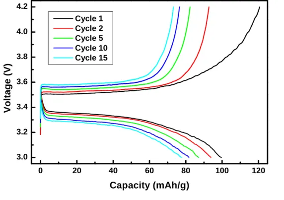
Figure 5‐3 Charge‐discharge profile for as‐prepared LiFePO4
Observation of the SEM images showed that although the particle was in range of 100s nanometer, they agglomerated together forming a huge bulk particle. In which would reduce the surface area needed to increase the LiFePO
4/FePO
4interface and decreased the lithium bulk diffusion path [59]. The polarization happened as the cycle growing was also a contribution of the reduced LiFePO
4/FePO
4interface.
The proceeding process was to check the reproducibility of these samples, thus we can get ‘almost the same’ property as we going into further experiment.
We proceed with 3 batches of this solid‐state method. The results of the replication of this process were examined for crystallinity phase and electrochemical test under 0.1 C rates. The results of X‐ray diffraction patterns could be seen in Figure 5‐4, in which all of it looks alike. If we take a careful
0 20 40 60 80 100 120 140 160
3.0 3.2 3.4 3.6 3.8 4.0 4.2
Voltage (V)
Capacity (mAh/g)
Cycle 1 Cycle 2 Cycle 5 Cycle 10
observation into it, we could notice the difference in the relative intensities for all those three patterns.
Figure 5‐4 Replication of solid‐state LiFePO4
Based on above results, we tried a different way to prepare our LiFePO
4sample. Since we notice that the problems that might occurs in our samples due to the amount of Iron that couldn’t be exactly controlled and the different state of vacuum, thus gave effects in the contact in between the iron and the oxygen that occur to be in the atmosphere. Later, we proceed by using high water dissolution material as the precursors; those were LiOH.H
2O, FeSO
4.7H
2O, and NH
4H
2PO
4as the precursor of lithium, iron, and phosphate, respectively.
1 5 2 0 2 5 3 0 3 5 4 0 4 5
J C P D S 1 s t b a t c h 2 n d b a t c h
Intensity (a.u.)
2 t h e t a
3 r d b a t c h
![Figure 3‐6 shows the actual of the olivine LiFePO 4 . The octahedral in this structure distinct in size and its crystallographic structure, thus favoring the MM’XO 4 [35], one is occupying the corner‐shared octahedral ‐ oc](https://thumb-ap.123doks.com/thumbv2/9libinfo/9122643.407282/18.892.168.683.157.430/octahedral-structure-distinct-crystallographic-structure-favoring-occupying-octahedral.webp)